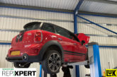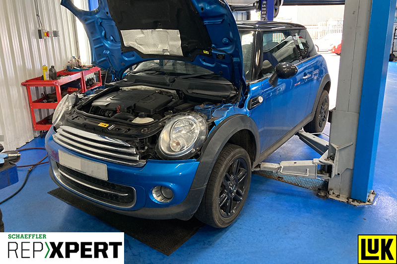
In this month’s Schaeffler LuK Clutch Clinic, REPXPERT Alistair Mason is replacing the clutch on a 2011 Mini Cooper D R56, along with the dual mass flywheel.
This 2011 Mini Cooper D was recovered to the workshop due to a non-start issue, which was soon diagnosed as a clutch fault because the clutch pedal could not be pushed to the floor to activate the clutch switch for the stop/start system. The vehicle had covered more than 111,000 miles.
The Cooper D is a popular vehicle, with around 200,000 registered in the UK. Being in the “super mini” category, they are popular with learner drivers and driving schools, which means that most examples will have tended to carry out short trips and will not have seen much motorway mileage, so it’s likely that many will need a clutch replacement during their lifetime.
This job makes a great repair for any independent, as with very little investment in tooling and a book time of 6.85 hours, it will give the workshop a great return.
Gearbox removal
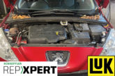
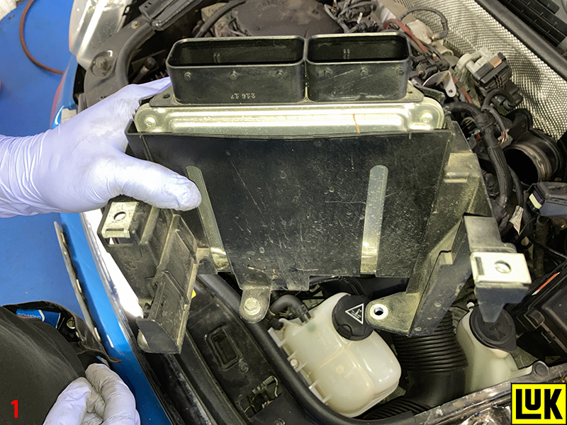
With the vehicle still sitting on the ground, slacken the front wheel/locking bolts and both the front hub/driveshaft nuts. Then open the bonnet and disconnect the battery earth lead, remove the engine cover and then the air box assembly. This gives good access to the engine ECU, which is removed as one unit by disconnecting the two multi-plugs and the ECU bracket retaining bolts located under the fuse box (Fig.1).
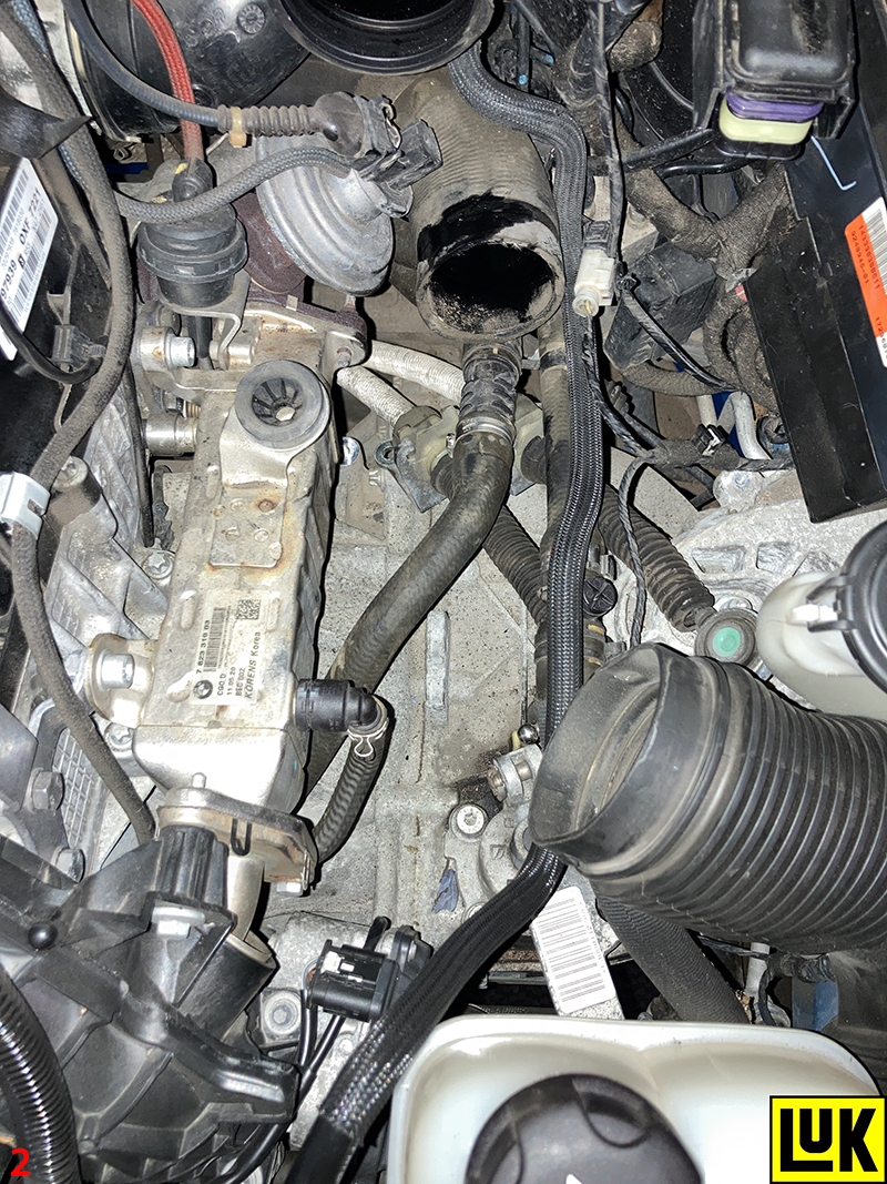
Next, remove the engine turbo boost pipe by first unclipping the coolant hoses from the top area and slackening the retaining clip on the rubber hose. After raising the vehicle lift and removing the engine undertray, slacken the boost pipe retaining clip on the intercooler and release the pipe from the rubber intercooler hose. Lower the vehicle lift and remove the turbo boost pipe, which gives good access to the top of the gearbox (Fig.2).
Disconnect the gear linkage cables, unbolt the cable retaining bracket, disconnect the reverse light switch multi-plug and remove the upper bellhousing bolts. Raise the lift to waist height and remove both front wheels and both hub/driveshaft nuts, then raise the ramp to gain access to the underside.
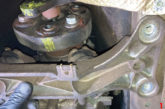
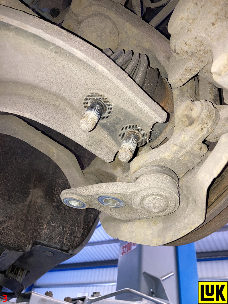
Next, the front subframe must be detached. Start by removing the complete exhaust assembly, then disconnect both bottom ball joints (Fig.3), both anti-roll bar links and unbolt the power steering rack from the subframe.
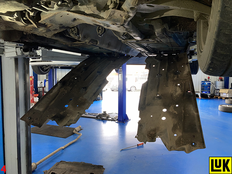
Ease down both plastic aero floors to access the subframe’s rear bolts (Fig.4), remove the lower pendulum engine mount (Fig.5), then support the subframe with a transmission jack.
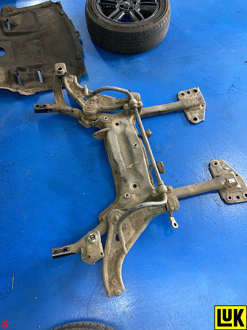
Removing the bolts, ease the subframe backwards and, once free, lower on the transmission jack and stow safely (Fig.6).

Drain the gearbox oil and remove both driveshafts. When removing the O/S driveshaft, the support bearing mounting must be unbolted from the engine block. Remove the clutch slave cylinder and stow away from the gearbox, disconnecting the multi-plug from the gear recognition switch on the front of the gearbox. Then, unbolt the power steering pipe retaining brackets and position the pipes away from the gearbox. Remove the lower bellhousing bolts, leaving one easily accessible bolt to support the gearbox.
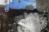
Support the engine with an engine support, unbolt the gearbox mounting from the gearbox, support the gearbox with a transmission jack and remove the final bellhousing bolt. Lower the engine and gearbox slightly to gain more clearance to aid gearbox removal and then ease the gearbox away from the engine. When the gearbox input shaft is clear of the clutch, lower the transmission jack and remove the gearbox.
Fault diagnosis
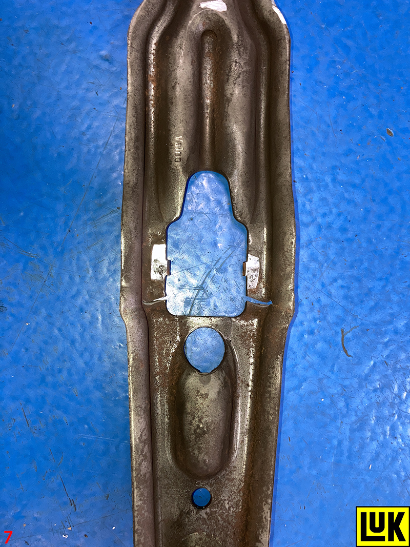
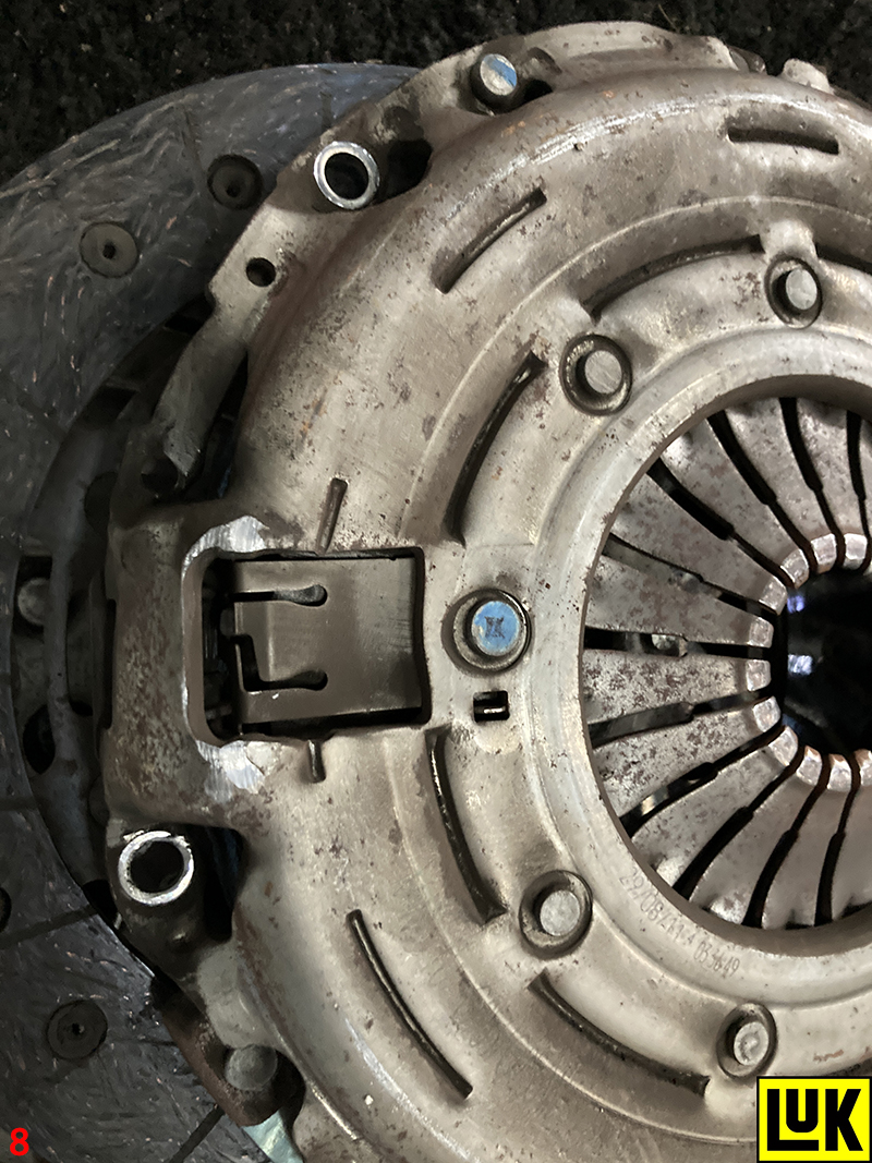
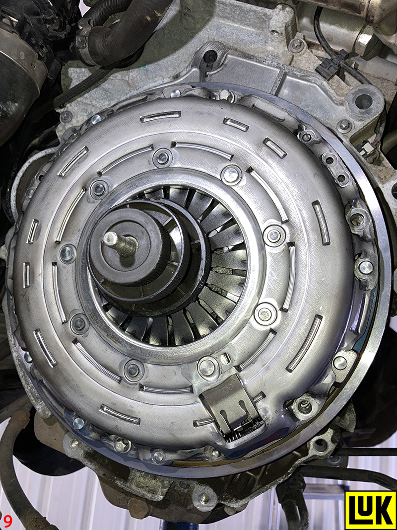
On inspection of the clutch and, more importantly the release system, the fault in this example was identified as the clutch release arm, which had cracked through (Fig.7), causing it to flex and hit the clutch pressure plate (Fig.8) and therefore was not able to provide a full master cylinder stroke.
At this point of the repair, the customer was advised of the repair costs for a new clutch, dual mass flywheel and a new release arm, and authorisation to carry out the repair was given.
Clutch replacement
Unbolt the clutch assembly from the DMF and then remove the DMF, inspect the back of the engine for any oil or coolant leaks that could contaminate the new clutch and DMF and rectify as required.
Check the parts for any service bulletins and obtain the correct torque settings by using the Schaeffler REPXPERT App, then degrease the face of the new DMF using clutch and brake dust cleaner, and replace the bolts with the new ones provided in the Schaeffler kit, torquing them to the manufacturer’s specification.
Turning to the gearbox bellhousing area, with the release arm already disconnected, remove the clutch dust using clutch and brake dust cleaner, check the release arm pivot point and release bearing guide tube for any wear and replace if required, then mount the new release bearing and arm onto the gearbox. Apply a light smear of high melting point grease to the splines on the gearbox input shaft and then mount the new clutch plate onto the input shaft, this will evenly distribute the grease and confirm the clutch plate is the correct fitment. Remove the clutch plate and wipe off any excess grease.
Degrease the face on the new clutch pressure plate with clutch and brake dust cleaner, then, using a clutch alignment tool (Fig.9), mount the new clutch plate noting the “Gearbox Side” identification, align the clutch pressure plate onto the DMF dowels, insert, tighten, and torque the clutch bolts.
Gearbox replacement
Ensure the engine to gearbox alignment dowels are located in the engine and that pipes and wires are clear, so as not to get trapped when the gearbox is installed. Using the transmission jack, ease the gearbox into position and locate onto the dowels. Insert and tighten an easily accessible bellhousing bolt, and using the transmission jack and engine support, align the gearbox with the gearbox mounting and tighten in position.
The remaining installation is in reverse order of removal, but remember to torque the required bolts to the manufacturer’s specification. After the battery lead has been reconnected, reset all electrical consumers and finally, always carry out a road test to ensure a high-quality repair has been completed.