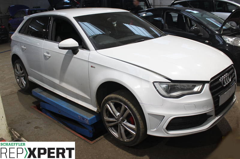
REPXPERT’s Alistair Mason replaced the clutch on a 2014 Audi A3 1.6TDI, using Schaeffler’s LuK 2CT repair solution, following complaints that the vehicle was juddering when pulling away and gear changes were harsh.
The gearbox unit was checked for fault codes, and two were confirmed: P177D and P279800. These were cross-referenced, and it was indicated that the clutch on the vehicle, with more than 140,000 miles on the clock, needed to be replaced.
Double-clutch gearboxes are becoming more popular in modern cars. Put simply, they are a manual gearbox and clutch system being controlled and operated by an electronic control unit. This means that the vehicle is always in the correct gear, and gear changing is almost seamless, which helps reduce the emissions, thus enabling the vehicle manufacturer to meet emissions targets.
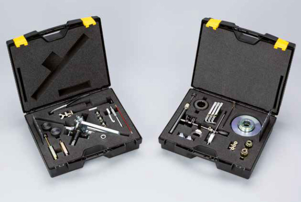
Schaeffler offers the complete repair solution for the dry clutch DSG gearbox: clutch kit – which includes every item required to replace and shim the new clutch– specialist tooling, IMI-certified training, full repair instruction manuals and REPXPERT repair videos. Replacing the clutch in an A3 can be completed in six-and-a-half hours. In terms of equipment, a twopost ramp, engine support, transmission jack, diagnostic tool with compatible software and Schaeffler’s 2CT DSG toolkit (see below) are required for this repair.
Step-by-step procedure
With the vehicle placed on the ramp, open the bonnet (see below) and remove the engine cover, air filter assembly, battery cover, battery and battery carrier.

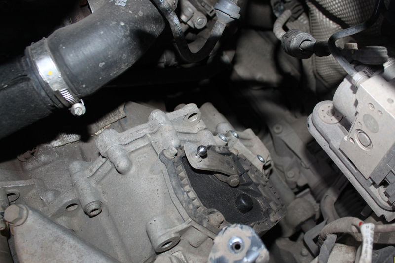
This will now give good access to the top of the gearbox (see below).
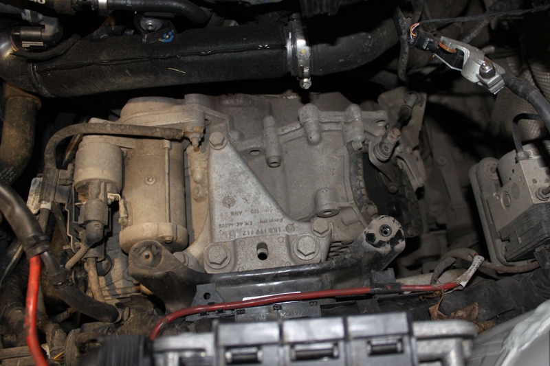
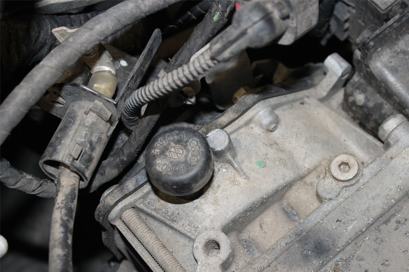
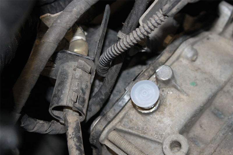
Disconnect the gear change cable and then remove the starter motor. An important procedure to carry out when removing this type of gearbox is to remove the breather caps from the gearbox and mechatronics unit, and then fit the blanking caps supplied with the DSG toolkit and replacement clutch kit. This will ensure that no oil leaks from the gearbox and, more importantly, from the mechatronics unit (see below).
At this point, remove the upper bell housing bolts. Next, raise the vehicle to waist height, and remove both front wheels and N/S/F wheel arch liner, before raising the vehicle to gain access to the underside.
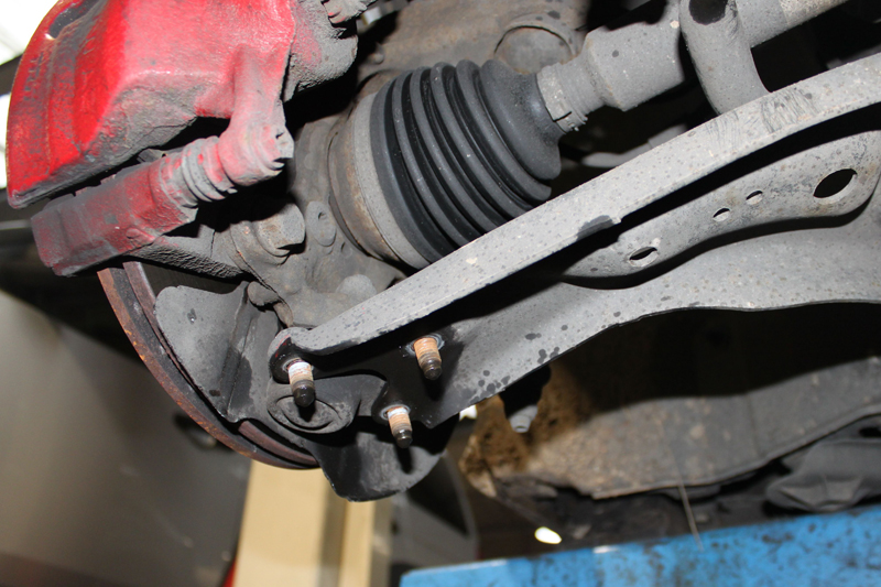
Now take away the engine under-tray and disconnect the wiring loom and bracket that connect to the mechatronics unit, located on the front of the gearbox. Next, detach the front sub-frame by releasing both bottom ball joints (see below), unscrewing the four bolts that hold the steering rack to the sub-frame and support the steering rack.
Remove the exhaust mounting and disconnect the anti-roll bar links and gearbox pendulum mount. Take the wiring loom for the oil level sensor and the auxiliary coolant pump, and stow them away in a safe area.
Next, support the subframe with a transmission jack, remove the four subframe bolts and then lower the
sub-frame on the transmission jack – once again, move it to a safe area. Remove the driveshaft-to-gearbox flange bolts on both sides, before securing the driveshafts away from the gearbox.
Removing the gearbox and clutch
To aid the removal of the gearbox, remove the driver’s side driveshaft flange by unscrewing both the centre bolt and the lower bell housing bolt. However, leave one main bolt, which is easily accessible, to support the gearbox. Steady the engine by using the support, then remove the gearbox mounting in the engine bay. Lower the engine support slightly to aid removal of the gearbox, and support the gearbox using a transmission jack.
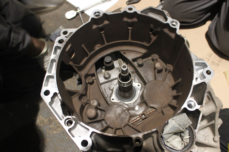
Now remove the accessible bell housing bolt and ease the gearbox away from the engine. Once it is free, lower the transmission jack and remove the gearbox from the vehicle. Place the gearbox on a suitable surface and attach the support leg which is supplied in the tool kit. The gearbox will then safely sit with the bell housing and clutch facing upwards, meaning attention can turn to removing the clutch:
■ Remove the clutch hub snap ring and clutch hub
■ Remove the clutch retaining snap ring from input shaft
■ Draw the clutch assembly off the input shaft using Schaeffler’s 2CT toolkit
■ Remove the two clutch engagement levers, shims and bearing
Upon completion, inspect the input shaft oil seals for any bearing play on the input shafts (see below).
Clean out the bell housing using brake and clutch dust cleaner to ensure the new clutch assembly remains uncontaminated.
The new clutch can then be installed:
■ Install the new clutch engagement levers
■ Follow the shimming process for both clutches using the pre-determined distance gauges and shimming gauge
■ Adjust the shims, if required, to the tolerances of that specific clutch (see below)
■ Install the new clutch using Schaeffler’s 2CT toolkit
■ Confirm the free play on both clutches is correct using a DTI gauge and then install the new clutch hub

Dual mass flywheel replacement
During this particular repair, the dual mass flywheel (DMF) was replaced (see below), and the new bolts were torqued to the manufacturer’s specifications – remembering that, when replacing the DMF, the flywheel must have the correct number of ring gear teeth and that there is a three-tooth difference between vehicles with conventional starting systems and vehicles with start/stop systems.
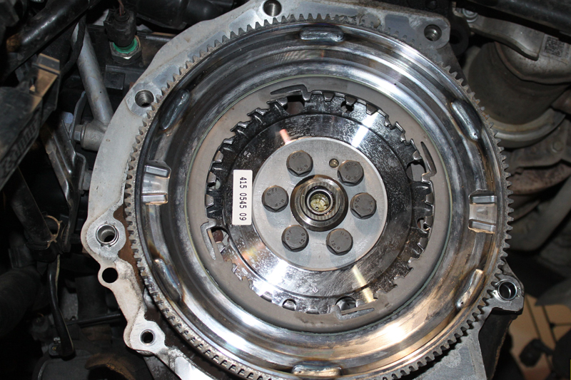
If the incorrect flywheel is fitted, basic setting and adaptions cannot be carried out correctly.
The gearbox can then be reinstalled in the vehicle (see below) in reverse order of removal.

Ensure all bolts are torqued to the manufacturer’s specification and replaced where necessary. Once installation is complete, the gearbox control unit needs to be reset with a compatible diagnostic tool.
Turn on the ignition and carry out basic settings on the gearbox control unit. Once complete, using the diagnostic tool, carry out an adaptive test drive to reset the gearbox control unit/mechatronics unit.