Introduced in 1997, the Mercedes A-Class has proven to be a popular vehicle with close to 50,000 vehicles on the UK’s roads. With a lengthy removal process, which is reflected in a removal time of more than seven hours, this handy article will prove to be an essential read for any garage in the UK aftermarket and will help to reduce the removal and installation time down to less than four hours.
No special tools are required to complete the repair, but you need to support the engine, gearbox and subframe. In this example, we used four transmission jacks, but, alternatively, you could use two jacks and some rope to support the subframe. A two-post ramp was also used for the replacement. If the vehicle has alloy wheels, they may be fitted with anti-theft locking nuts, so make sure you have the key before starting the repair.
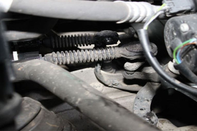
Open the bonnet and, for safety reasons, disconnect both battery terminals. Remove the washer bottle for easy access and undo the steering column assembly. Unlink the gear selector cables from the gear mechanism and completely remove them from the securing bracket before stowing away safely to one side (Fig 1 below).
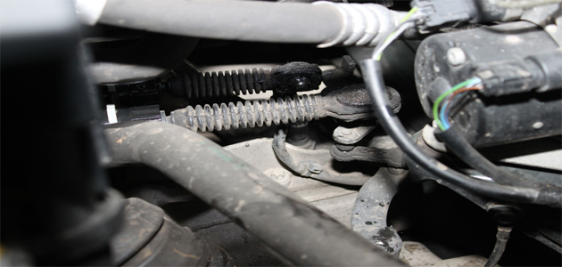
(Fig 1)
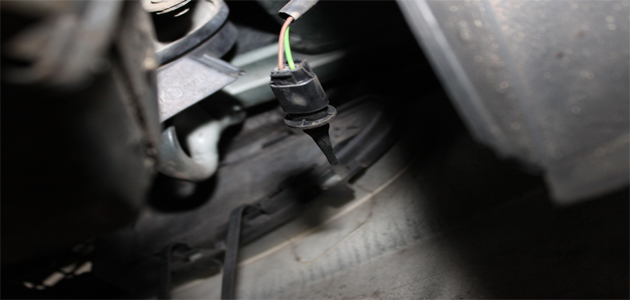
Disconnect the reverse light switch and remove the earth connection from the gearbox mount (Fig 2 below).
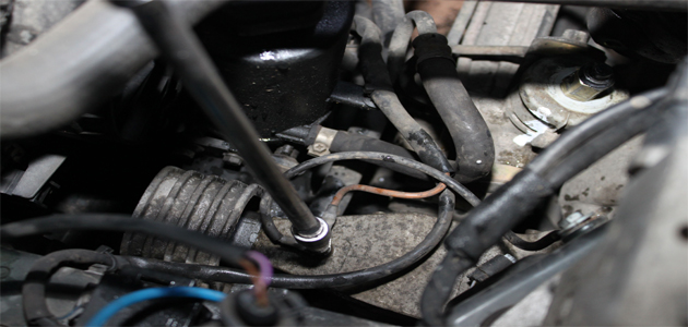
(Fig 2)
Raise the vehicle
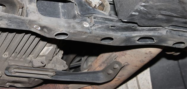
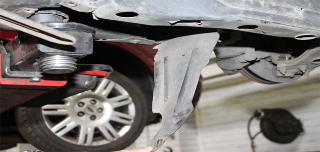
Support the radiator and fan assembly to the body using cable ties, as you have no need to remove them or drain the coolant. Remove both front wheels, then raise the vehicle to full working height and drain the gearbox oil. Remove the subframe protection covers from the left and right hand sides (Fig 3 below).
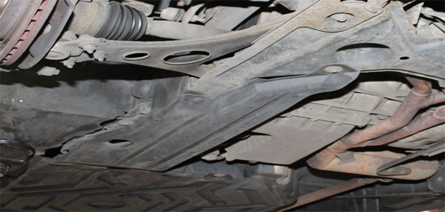
(Fig 3)
Slacken the ball joints on both sides and then remove both brackets that hold the anti-roll bar in place (Fig 4 below).
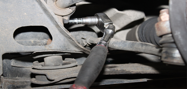
(Fig 4)
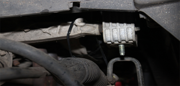
Remove the bracket that attaches the exhaust to the gearbox (Fig 5 below).
(Fig 5)
Next, remove the left and right-hand side brackets that attach the front bumper to the subframe, taking note that the right-hand bracket houses the ambient temperature sensor, which must be disconnected and safely stowed (Fig 6 below).
(Fig 6)
Support the engine, gearbox and subframe using four axle stands, whilst removing the fixing bolts to the subframe. Remove the gearbox mounting nut and the two engine mounting nuts from the brackets attached to the subframe (Fig 7 below).
(Fig 7)
At the rear of the subframe you will find two further brackets that attach to the underside of the body that need to be removed on both sides. Remove the central through bolt, engine rear mount and gearbox rear mount. Remove six subframe bolts that attach to the body, and then remove the left and right-side steering rack to subframe brackets.
Remove the steering pump from the subframe by loosening the hexagonal bolt, and the pump will slide up from the bracket on the subframe. Undo the wheel arch liner flap on the left-hand side (Fig 8 below) to expose two further bolts and the A/C pipe bracket and remove.
(Fig 8)
Safely stow the power steering pipes, detach the steering rack from the subframe and carefully lower the front of the subframe using the two axle stands – or rope – as support.
Store away safely
Release both ball joints, carefully remove the complete subframe and move away and store safely from the work area. Support the steering rack and pump securely. Disconnect the hydraulic pipes for the CSC, before blanking and stowing away securely. Remove the gearbox mount bracket.
Remove the bolts that secure the driveshaft to the gearbox and remove the drive shaft. Remove the starter motor bolts and stow to one side. It’s worth noting that the bolts for the starter motor are torx bolts. Remove nine bolts that secure the bell housing, and carefully lower the gearbox and move away from the work area.
You should now have enough clearance to remove the clutch. With the clutch removed, check the flywheel for signs of heat stress or excessive wear. Clean the first motion shaft splines and any debris from the bell housing.
Put a small dab of high-melting point grease – not a copper-based product – on the first motion shaft splines, and make sure the new driven plate slides freely back and forth. This not only spreads the grease evenly, but also makes sure you have the correct kit. Wipe away any excess grease off the shaft and driven plate hub. Using a universal alignment tool and checking the driven plate is the correct way round, the clutch can be bolted to the flywheel evenly and sequentially.
Make sure any dowels have not become dislodged or damaged and replace any that have. Install the gearbox and make sure the bolts are secured and all mountings are refitted before removing the supporting transmission jacks. Refitting the rest of the components is the reverse of the removal, not forgetting to refill the gearbox with the correct grade of oil.


