When replacing a suspension component, all other parts of the system should also be thoroughly inspected for wear, says Tim Hodgkin, Technical Support Technician at ZF Services UK, to maximise safety and prolong the life of newly fitted items.
Shock absorbers maintain tyre-to- road adhesion for good grip and braking. If they or other suspension components are worn, optimum contact is reduced, resulting in longer braking distances and compromised handling, especially during critical avoidance manoeuvres. Also, vehicle safety systems such as anti-lock braking and traction control can only function perfectly if all suspension elements are in faultless condition. It is for this reason that a full and detailed check of all parts of the system is so important when replacing any suspension component.
Check everything
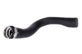
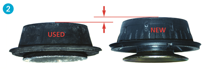
Taking the example of fitting a new shock absorber, the condition of ball joints and rubber-to-metal components, such as control arm bushes (see Fig 1) and suspension top mounts (see Fig 2), should be checked before or during dismantling. Wear in any of these areas can lead to excessive play in the joints, subjecting the shock absorber piston rod to bending stresses beyond its design limits.
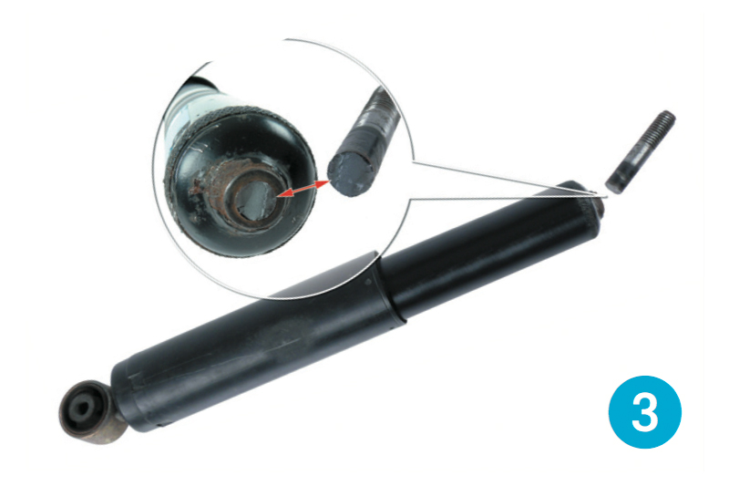
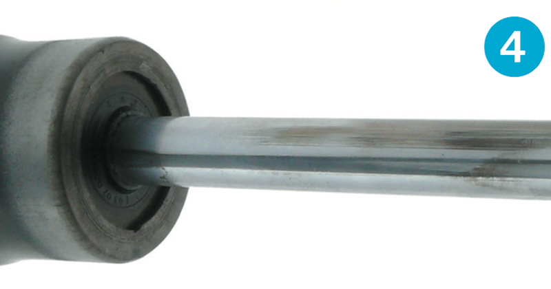
One possible consequence is that the threaded pin suffers a fatigue fracture where it joins the piston rod (see Fig 3). Another failure mode is the side loading of the piston rod rapidly wearing both its chromium plating (see Fig 4) and its oil seal, causing the shock absorber to leak.
Overhaul or replace?
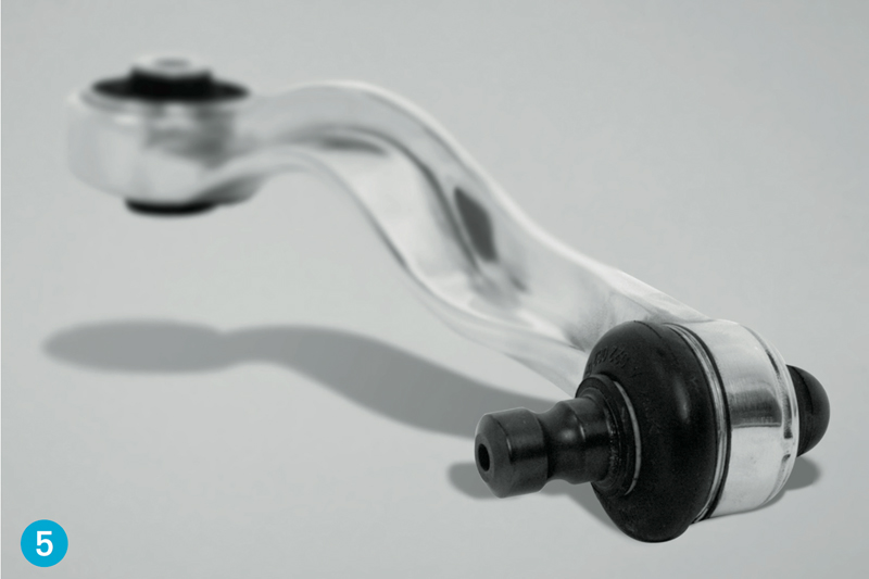
To preserve fuel economy and minimise emissions, vehicle manufacturers increasingly specify lightweight aluminium alloy forgings for suspension components, such as track control arms (see Fig 5).
Faced with weight constraints, the designer may create the part with the intention of it being replaced when wear occurs, rather than overhauled. Vehicle repairers should therefore check whether the manufacturer of the vehicle or component recommends that aluminium control arms are replaced as complete assemblies.
Even using a hydraulic press and the correct press tools, driving out old bushes and inserting replacements can tear out minute alloy fragments from the bush housing, leaving a less stable joint. Plus, the risk of nicking the alloy with a tool in the process and forming a nucleus for stress concentration could ultimately cause a fatigue failure.
Replace in axle pairs
When replacing any suspension components, a basic rule is to always replace in axle pairs to maintain safe, balanced handling and ride comfort. Replacing in pairs is even more critical when the design parameters of a replacement part have changed with ongoing product development.
OEM/OES compatibility and supersession benefits
Insisting on original equipment parts not only ensures compatibility with the original vehicle specification, but also confers the benefits of any component modifications or upgrades made by the manufacturer. An example of supersession in a suspension component is the Lemförder rubber-to-metal front subframe bush used in several VAG vehicles – Seat Cordoba (6L2), Seat Ibiza IV (6L1), Skoda Fabia (6Y2, 6Y3, 6Y5), VW Fox (5Z1, 5Z3) and VW Polo (9N).
The original part number 29710 01 (see Fig 6.1) has been replaced with an improved design, part number 34559 01 (see Fig 6.4). Unlike the original, the new bush does not have a raised rubber plug (see Fig 6.2) to align with a corresponding mark on the front axle support (see Fig 6.7 – this is cast below the bush housing on the right-hand side of the vehicle, and above the housing on the left-hand side).
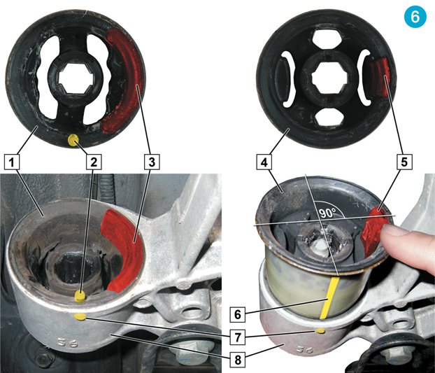
The absence of the reference point could be misconstrued as meaning alignment is unnecessary following the redesign, but to achieve the desired handling and ride characteristics, it is important the new bushes are correctly oriented during installation.
To achieve this, the area on the bush where the control arm makes contact (see Fig 6.5), must point to the axle support or towards the centre of the vehicle. A mark (see Fig 6.6) can be made on the bush at 90 degrees relative to the contact area, which is then aligned with the mark on the axle support before pressing the bush into position with suitable tooling.