Automotive Application Specialist, Ben Martins, was recently asked to join an old work friend to take a look at a new type of air flow sensor that, for now, has only been seen on the Ford EcoBoost engine. The fact that it is a 4-wire type that has a 12 V supply from the same fuse that the fuel pump gets its supply from makes it intriguing.
The vehicle was a 2014 B-Max, 1.0L, 3-cylinder, turbocharged petrol engine. It had been brought in as the EML was on with the fault code P0102 Mass Air Flow MAF Circuit Low. So, first things first, we checked the sensor plug for security and pin integrity. A great tip here is to use a breakout lead to check the resistance of the pin. By using the male ends we can check to see if there is any issue with the connection between the pins. In this instance there was an issue with one of the pins in the plug, giving us the impression that it had already been looked at somewhere else. After further chats with the customer, we learned that the vehicle had already been fitted with a replacement MAF sensor – the plot thickens.
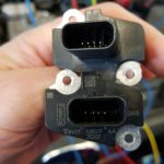
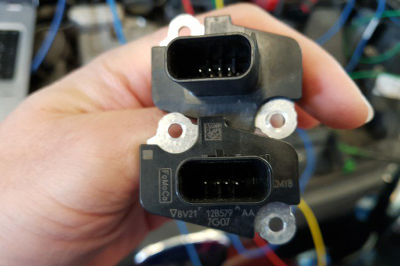
Luckily, the customer had asked to have the old one back when replacing it didn’t work. The replacement sensor was a pattern part and not a genuine sensor, which seems to be a growing trend. In this instance, it hadn’t been sold as a genuine part but everything looked the same, only the manufacturer numbers had been ground off. Be careful when fitting pattern parts as the sensors will vary and can have adverse effects on the signal.

We turned our attention to the wiring diagram. As I explained earlier, this MAF sensor is a 4-wire type which isn’t unheard of if it was just a MAF sensor. However, like all modern MAFs this one also has an intake air temperature sensor built in. This makes it different, as these types of sensors usually come with six wires. Oddly enough though, the plug is still the same as the 6-wire type.
When we study the wiring diagram, some more unusual aspects become visible. Commonly, with most 6-wire MAF sensors, we tend to see 12 V (Batt), 5 V from PCM, MAF return signal to PCM, Intake Air Temp 5 V, Intake Air Temp Return and an Earth. As you can see below, we have a 12 V feed, Ground and the two return signals for MAF and IAT. What is also strange is that the 12 V also supplies the fuel pump.
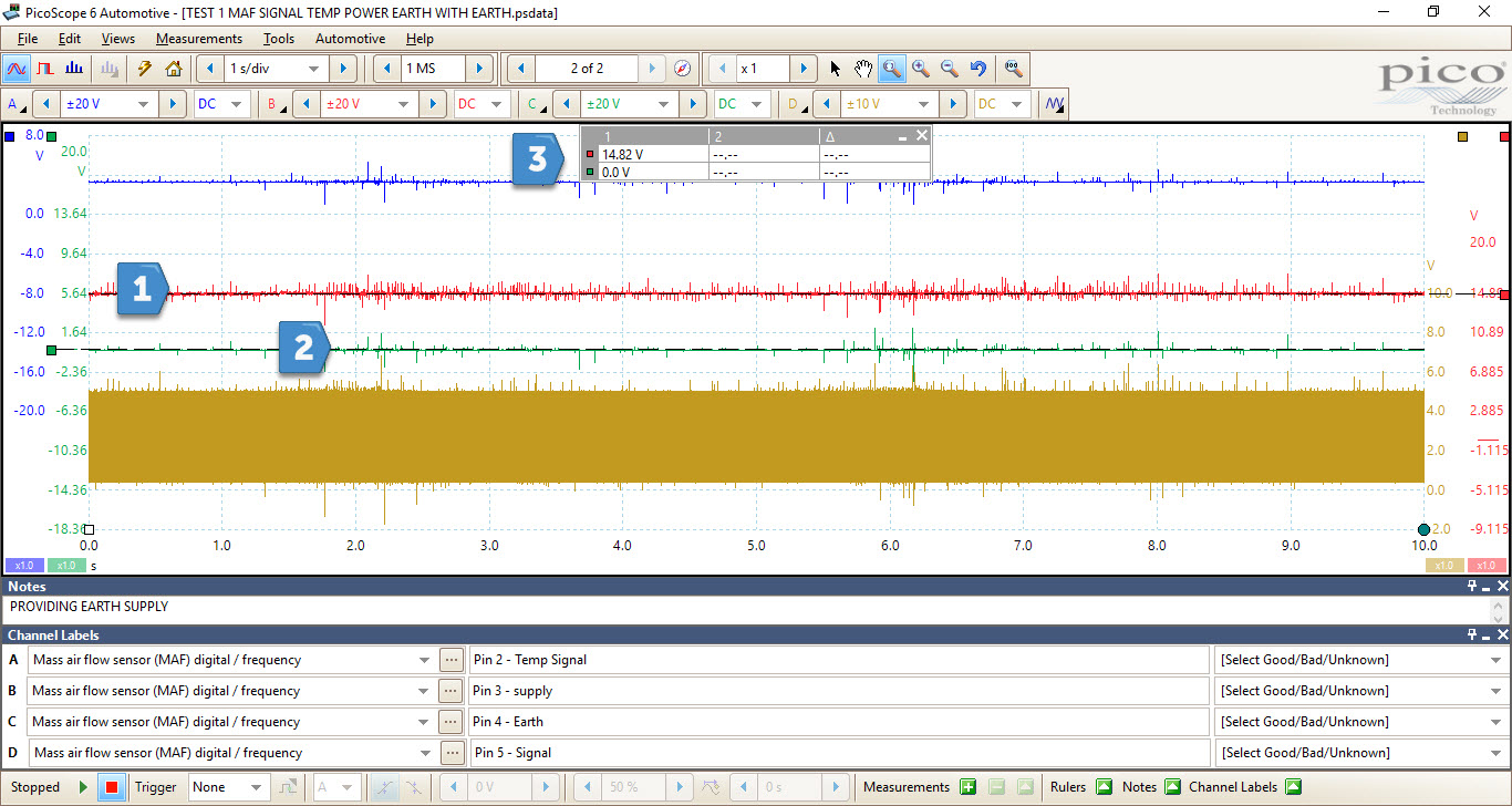
 As we had a 4-channel scope to hand and four wires to the sensor, it made sense to take advantage of this and look at all four signals together. With the ignition on, it quickly became clear that we didn’t have a 12 V supply to the MAF sensor. The fuse was fine and the engine started and idled, so we were happy that the wiring down the fuel pump was ok. Now we had to face the ultimate challenge for any workshop, locating a broken wire. Fortunately, we were lucky. When we removed the air filter box we found the bit of loom that had the break and this was quickly repaired.
We cleared the codes and checked the voltage supply to the MAF sensor. 12 V – happy days, but now we had some new codes: P0101 MAF Air Flow Sensor Circuit Range/Performance and P0113 Intake Air Temperature Sensor 1 Circuit High Input. At least the IAT is being recognised by the ECU, which is more than it did earlier. With all four channels still up and the ignition on, we took another look at what was going on.

- 12 V supply
- Earth from ECU
- Signal rulers
We can see the battery voltage with the engine running at 14.7 V, but the earth, which is supplied from the ECU, is at 12 V. This is not correct and it may even be open or at least at a very high resistance. Not only this, but the MAF sensor is a digital type which is obviously not present on channel D. With a timebase of 2 s/div, we would expect to see a block of yellow. With no real idea as to what is going on, there should be something.
In the waveform above we have nothing present. We turned our focus to the earth circuit. Finding the pin at the ECU was easier said than done. I don’t think I’ll ever get used to being upside-down in the footwell of a car, with a torch between my teeth, a back-pinning probe in one hand, while the other hand wrestles with a wiring loom that feels like it was moulded after it was fitted to the car.
Just to make things more complicated, the resistance was minimal in the wire measuring with 0.2, and a check against the other wires and to ground all resulted in an open circuit. Now we were left with one last component, the PCM. No one ever likes to condemn an ECU because if you fit it and the fault is still there you are now the proud owner of a £1000 piece of metal. Because it is not the most common component to replace, we checked and doubled checked our connections and the tools to be 100% certain that there was no way an earth signal was sent from the ECU to the MAF sensor. Happy that this was indeed the case, we phoned the local dealership for a price and had to sit down. £1200 +VAT! Well, I guess that was to be expected.
The answer to our next question, however, was somewhat more surprising and one that raised a few eyebrows. How long would we have to wait? “We have one on the shelf and can drop it out today if you need it.” Not something you hear every day and it does make you wonder why a dealership would be holding stock of a £1200 ECU. Perhaps there is something going on that we don’t know about?
To be completely confident with our diagnosis we had one last thing to try: to provide the MAF sensor with a direct earth. As we already had the leads in place we placed a jumper lead between the battery earth and the MAF earth terminal. We crossed our fingers and turned the ignition on – no EML. We started the engine and the results spoke for themselves:
- 12 V supply
- 0 V – earth supply
- Ruler overview
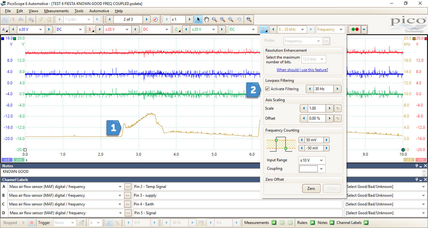
We now had our supply, an earth, and most importantly a digital signal from our MAF sensor as we would normally expect. There were a couple of ways we could display this signal. We could utilise the Frequency coupling mode and look only at the output of the MAF as a frequency. This is great as we can then see what we would normally expect a MAF signal to look like.

You can see the amount of noise present with this type of coupling, but by using the filtering feature we can eliminate these spikes. This forum post illustrates some of the ways we can graph a digital signal. There is also some great information regarding Frequency coupling which you can find here.
Just remember that we can apply filtering post-capture, so always capture without and clean it after.
The other option is to use math channels. These can also be done post-capture and you can add as many as you like without upsetting the original data capture.

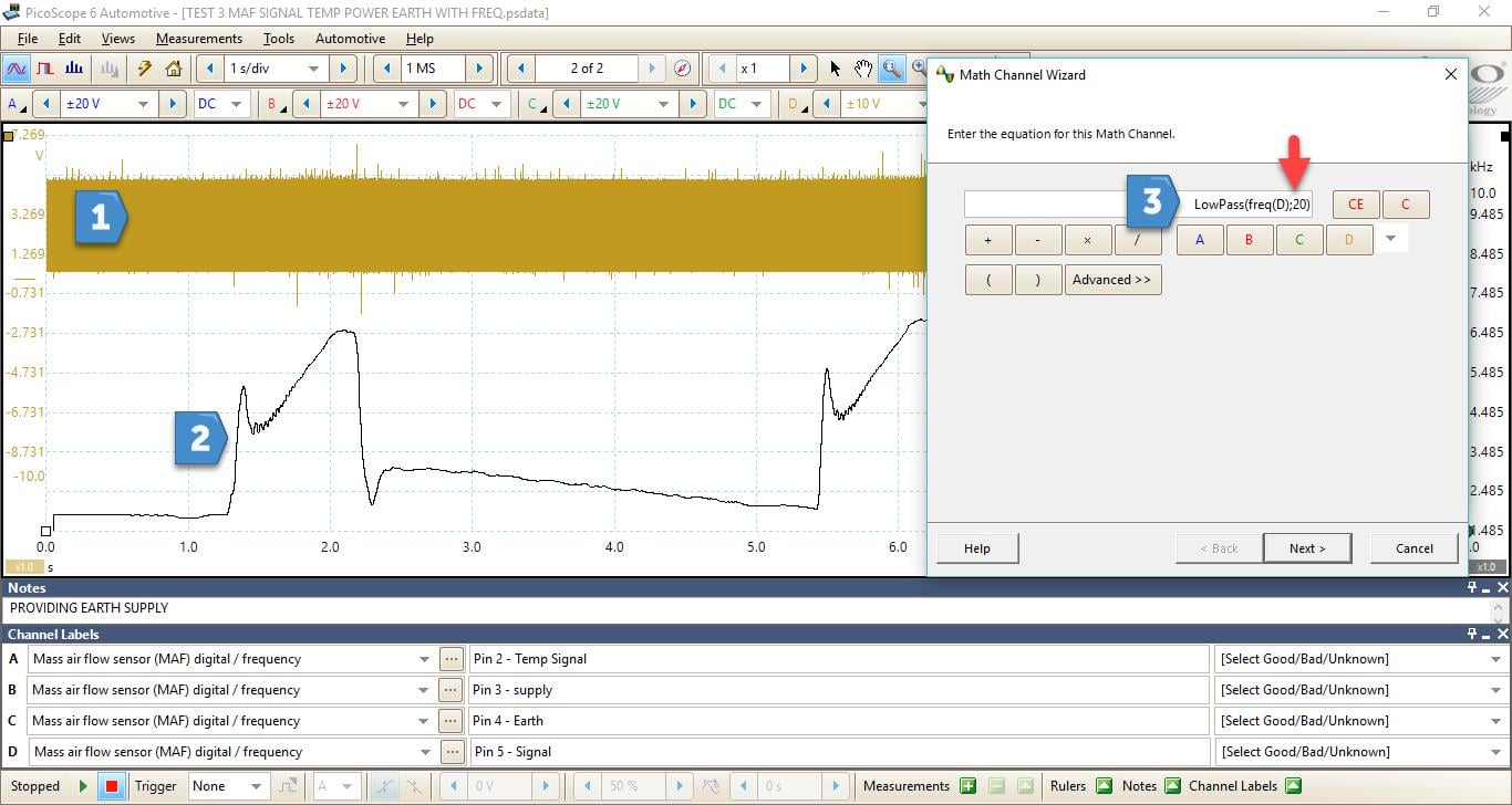
- Digital signal
- Math channel showing MAF response to snap throttle
- Math channel wizard
Now we have a much cleaner image. You can see the initial gulp of air from the engine as the throttle is opened, followed by the gradual rise in MAF as the engine RPM increase during a snap throttle event. To help smooth the math channel I’ve added a lowpass filter to the formula. It now reads LowPass(freq(D);20). Altering the number at the end of the formula will increase or decrease the filtering. The lower the number the more excessive the filter.
Armed with the information gathered so far, we were happy that the sensor was performing as it should with the addition of a ground signal. This can, of course, be seen as a little overkill but I’ve been in the horrible position where you have that ECU in your hand and you’re thinking what if this doesn’t fix it. I like to be sure that there is nothing more I can test to be confident that this is the right part to replace. In this instance, it is the only thing supplying earth to the MAF so it has to be the answer.
To complete process we gave the following options to the customer: Would you like us to create an earth for the sensor or would you prefer us to fit a new ECU? You can guess which option the customer went for.


