In the previous article Tom Denton described equipotential bonding (EPB) as the process of connecting all metalwork and conductive parts, of various components, so that the voltage is the same throughout these various parts (an equal potential). EPB is used to reduce the risk of equipment damage and personal injury. This time he will look at how the tests are carried out.
Checking that the EPB is meeting regulations, is something that could become more common as more high voltage vehicles hit our workshops. It could also be a new income stream.
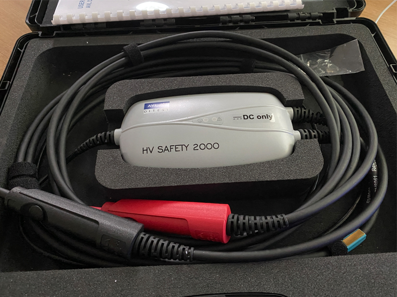
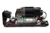
The EPB testing equipment shown as Fig.1, is computer-based so generates a results which are saved after each measurement. These results are dated and linked to the vehicle and technician, as proof that tests have been carried out by a specified person using calibrated equipment, at a specific date and time.
In principle the EPB test is simple, a known current (up to 1 A as per ECE R100 regulations) is made to flow and the voltage is measured. Resistance (R) is then calculated using the current flowing (I) and the measured voltage (V) using the formula: R=V/I.
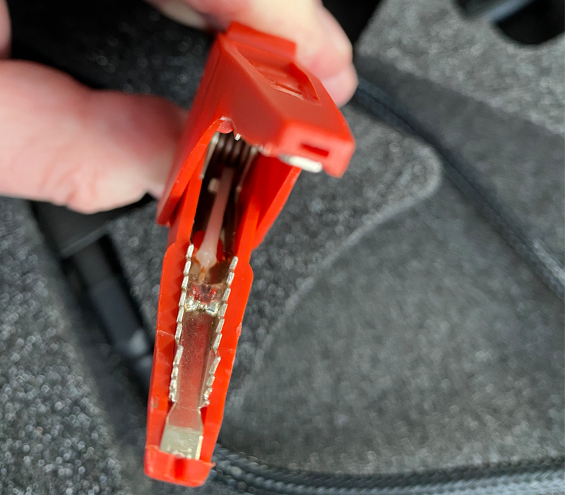
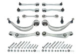
‘Kelvin leads’ can be used, so the voltage at the test points is measured using a separate circuit to the one where the current is flowing. The special crocodile clip (Fig.2) has each jaw insulated from the other. The clip is therefore attached to a twin core insulated cable.
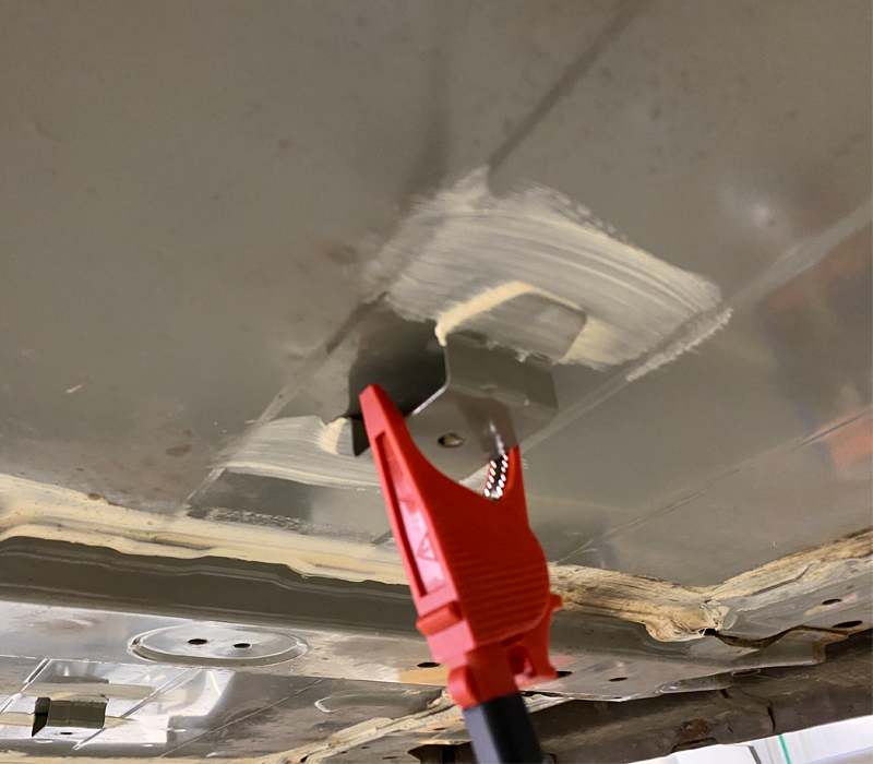
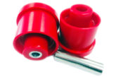
My colleague Eliot Smith and I tested the AVL DiTEST HV Safety 2000 on a Nissan Leaf. To even see the battery pack on a Nissan Leaf, a large protective cover has to be removed – not difficult but it does take time. The pack is painted and, as this is an older car, it was also a little corroded and dirty. We connected one lead (Fig.3) after scratching a small amount of paint off (which was replaced!). In this way the connection is definitely to the actual pack rather than a bolt or strap.
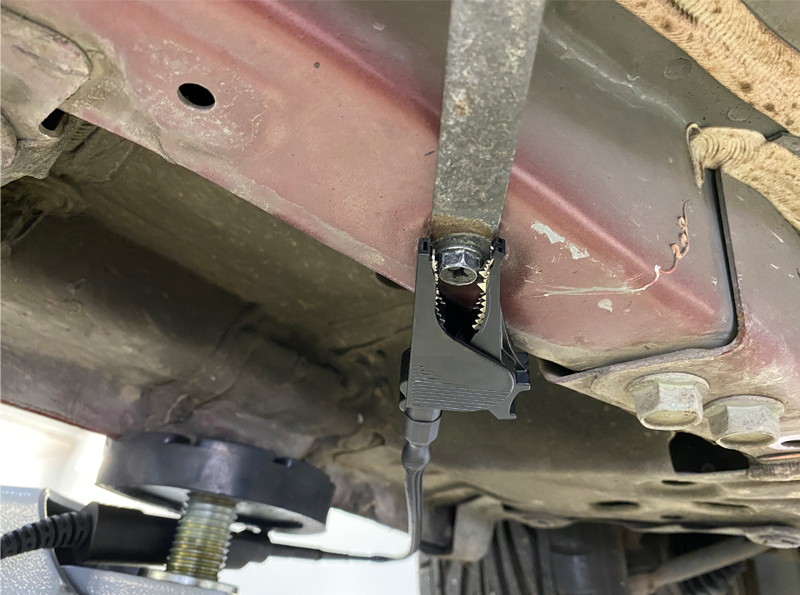
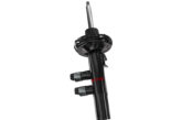
We cleaned a chassis bolt and made the other connection (Fig.4). In this way, if the result was as required (less than 100mΩ) it would prove a low resistance circuit between the battery case and the vehicle chassis. Our result was 5mΩ, so well within specifications.
Checking the EPB on the motor and other components was simpler because they were easier to access. One connection to the chassis, and one to the body of the motor after the area was cleaned. We got a result of 8mΩ.
Using the specialised equipment ensured accurate tests and kept a record. However, it is possible to complete an EPB test using a battery and variable resistor, together with an accurate ammeter and millivoltmeter. Make a circuit that causes 1 A to flow through the item under test (battery case as above) to the chassis. Measure the volt drop and calculate the resistance. Dated photographs could be used to keep a record.
Because of the time involved in removing covers or access panels, we felt it would not be appropriate to carry out a full set of tests after every repair. However, if asked to carry out safety tests after major accident damage or other repairs, then EPB checks will be essential. These tests may also become a requirement at some point.