
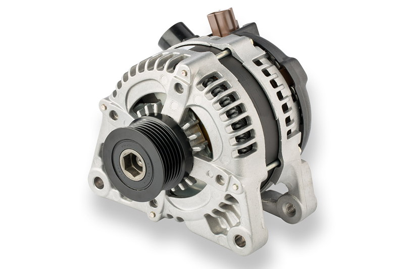
Denso takes a look at whether alternator diagnosis is becoming more complicated due to modern charging systems and how workshops should carry out testing.
In short, alternators are becoming more of a complicated diagnosis because modern charging systems don’t necessarily maintain the simple, relatively constant charging voltage they used to. So, how should workshops test modern alternators and distinguish an alternator fault from a battery, wiring, belt drive, control or energy management problem?
Diagnosing modern alternator systems is more complex because many vehicles now use smart charging systems where the alternator regulator communicates with the engine ECU, and charging voltage is intentionally varied according to driving conditions, battery state and electrical load. Modern systems can even reduce charging during acceleration and increase it during deceleration to improve fuel economy.
DENSO therefore recommends a systematic approach:
- Start with the battery
Before diagnosing the charging system:
- Visually inspect the battery and terminals
- Fully charge the battery
- Verify open-circuit voltage is 12.6V or above
- Carry out a battery load test if the battery voltage is satisfactory. A weak or defective battery can mimic charging system faults
- Perform a visual inspection
Check:
- Drive belt condition, alignment and tension
- Wiring integrity
- Clean, secure and corrosion free connections
- Alternator grounding
- Signs of physical damage, contamination or overheating
This helps identify belt drive, wiring and installation issues which can appear to be alternator failures.
- Carry out voltage-drop testing
To rule out wiring and connection faults:
Positive side (output circuit)
- Measure between the alternator B+ terminal and the battery positive post
- With engine at around 2,000 rpm and electrical loads switched on, voltage drop should be less than 0.2V
Negative side (ground circuit)
- Measure between the alternator casing and battery negative post
- Voltage drop should be 0.2V or less
Excessive voltage drop points to poor connections, damaged cables or grounding problems rather than an alternator defect.
- Check regulated voltage and output current
With the engine running at approximately 2,000 rpm:
- Verify regulated voltage at the alternator output terminal (B+)
- Measure output current with major electrical loads switched on
- Compare readings against the vehicle manufacturer’s specifications
These tests determine whether the alternator is producing the required output.
- Use a test bench if necessary
If vehicle testing is inconclusive:
- Test the alternator on a bench
- If output is within specification, the fault is likely elsewhere in the charging circuit or vehicle electrical system
- If output is outside specification, replace the alternator
- Use a scan tool on smart charging systems
For modern charging control and Stop/Start vehicles:
- A scan tool is required to separate system, ECU/regulator and alternator faults
- Active tests and monitoring functions can determine whether the issue lies in the alternator itself or in the control system
- Check alternator ripple with an oscilloscope
An alternative test is to observe the alternator’s ripple pattern:
- A normal ripple pattern indicates correct diode and stator operation
- Abnormal ripple patterns can reveal open or shorted diodes or stator winding faults
Distinguishing alternator faults from other causes
| Symptom | Possible Cause |
| Low or no charge with high voltage drop | Wiring, connections or grounding fault rather than alternator failure |
| Intermittent charging | Loose belt, poor battery connection, poor ground, wiring fault or regulator issue |
| Battery repeatedly flat | Defective battery or parasitic drain, not necessarily an alternator problem |
| Alternator overheating/failure | High resistance in charging circuit, poor connections or faulty battery causing excessive charging load |
| Incorrect charging voltage on smart systems | Possible ECU, LIN communication, regulator or energy-management issue rather than alternator hardware failure |
Key takeaway
Modern alternator diagnosis should not rely solely on charging voltage readings because smart charging systems deliberately vary output. Workshops should evaluate the battery, belt drive, wiring, voltage drops, alternator output, ripple pattern and ECU-controlled charging functions using a scan tool before concluding the alternator itself is faulty.