Febi explores the cause behind a common issue affecting vehicles after a new turbocharger has been installed. This relates to parts 190678 and 197135, affecting BMW 1 Series (F20, F21) 116i, 118i, 2 Series (F22, F23) 218i, 3 Series (F30, F31) 318i, 4 Series (F32, F36) 418i.
Problem
Coolant leak at the manifold shortly after installation of the new turbocharger.
Cause
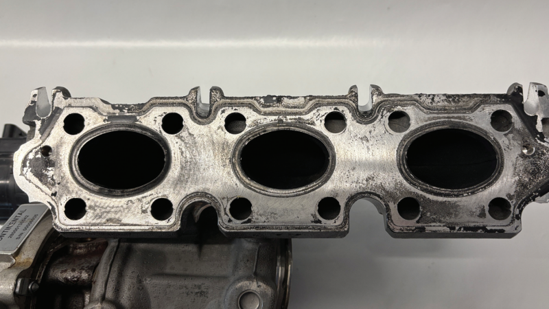
The seal between the cylinder head and the turbocharger is leaking. The turbocharger’s exhaust housing was originally engineered using an aluminium alloy to allow its integration into the engine’s coolant circuit. Consequently, the cylinder head features coolant passages near the exhaust ports.
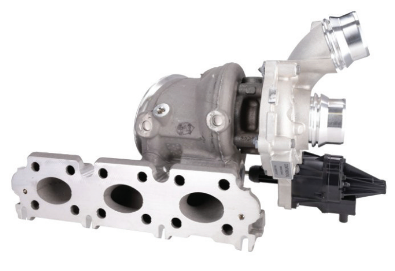
These are sealed, together with the exhaust ducts, by a single gasket. Another distinctive feature is the mounting of the turbocharger. It is clamped to the underside of the manifold solely by means of a clamping strip and keyways. As such, the manifold must be carefully aligned with the cylinder head during installation to guarantee a proper seal. Note: The clamping strip does not need to be loosened for the turbocharger to be removed.
Solution
To avoid coolant leaks, it is essential to follow procedure and specific tightening instructions:
-
Ensure all mating surfaces are clean and free from any debris or corrosion before assembly.
-
Check the turbocharger feed and return lines for contamination and obstructions and clean or renew as necessary.
-
Replace the engine oil and filter.
-
Check the condition of the air filter and replace as necessary.
-
Replace all necessary gaskets.
Before installing the turbocharger, use a syringe of motor oil to fill the oil inlet and rotate the turbine shaft. Position the new turbocharger into the clamping strip, aligning the keyways, then angle the assembly forward against the cylinder head.
The sequence for tightening the nuts is shown below. This process must be carried out in the following five stages: Tighten all nuts to 10 Nm, then repeat 10 Nm, then tighten all nuts to 16 Nm, then repeat 16 Nm, then repeat 16 Nm again.