Blue Print recently received a VW caddy into its workshop with its owner reporting all the classic symptoms of a worn-out clutch.
The Volkswagen Caddy, a versatile LCV that’s now in its fourth-generation, was launched in 1982 as a small pickup based on the Mk1 Golf. A well-known model sold internationally; the Caddy has always shared numerous mechanical components with other Volkswagen Group vehicles that will be more than familiar to workshops.
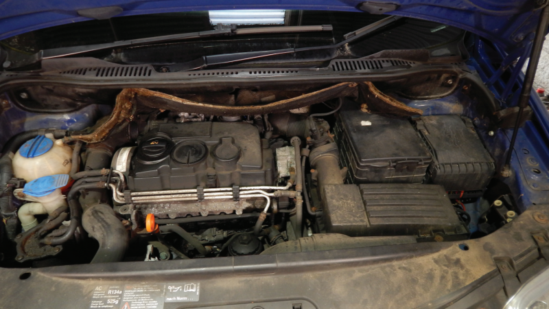
Recently, a third-generation Caddy van powered by the 2.0 TDI engine partnered with the five-speed manual transmission arrived in the Blue Print workshop. Its driver was reporting the typical symptoms of a very worn and slipping clutch, perhaps unsurprisingly with an impressive 271,000 miles (436,132 KM) under this hard-working LCV’s wheels.
Gaining access
Once the vehicle was brought into the workshop, the bonnet was opened and the battery, battery tray, and air cleaner assembly were removed to allow access to the top of the gearbox. This revealed the gear selector, clutch slave cylinder, starter motor and gearbox mounting (Fig.1).
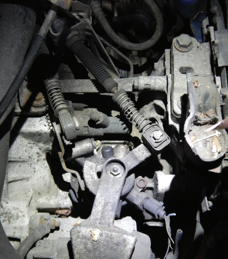
Fig. 1
The gear selector cables were unclipped from the selector levers and the three retaining bolts removed from the cable bracket, with the cables put to one side. The clutch slave cylinder was then unbolted and secured, followed by the reverse lamp switch, wiring harness, and starter motor, leaving only the gearbox retaining bolts in place.
An engine brace was brought in to support the engine, allowing the two bolts that hold the gearbox mount in place to be removed.
Lifting the vehicle
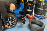
The vehicle was then raised to a working height and the front wheels were removed, followed by the left-front driveshaft retaining bolt, both lower suspension arm swivel joint retaining bolts (Fig.2), and finally, the left-hand wheel arch liner.
The inner driveshaft joint retaining bolts were undone which allowed the driveshafts to be pulled free from the drive flanges. The right-hand driveshaft was then secured to one side, and the left-hand driveshaft was removed completely to give clearance for the removal of the gearbox (Fig.3).
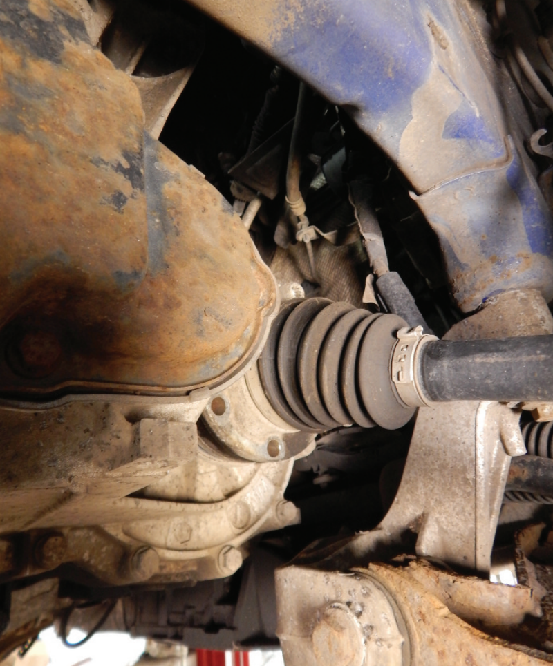
Fig. 2
Moving underneath the vehicle, the gearbox mounting was removed along with the small gearbox shield above the right-hand driveshaft, leaving only the upper gearbox retaining bracket and the lower gearbox retaining bolts in place.
Lowering the gearbox
The engine and gearbox were lowered to an appropriate position and the mounting bracket was removed. Then, with the gearbox supported, the last retaining bolts were taken out, allowing the gearbox to be dropped down and taken out of the vehicle.
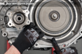
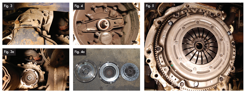
The clutch pressure plate, friction disc and flywheel were removed and inspected. This revealed that both the clutch assembly and release bearing were very worn, with the latter notably sticky in operation due to the amount of clutch dust that had accumulated within the housing (Fig.4). The conclusion was that the complete clutch kit needed to be replaced.
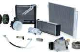
To carry out this work, Blue Print SMARTFIT Conversion Clutch Kit ADV183059 was chosen; a complete four-piece dual mass flywheel conversion kit which includes the torsion-damper friction disc, pressure plate, solid flywheel, grease, release bearing, all necessary bolts, and a SMARTFIT installation sticker.
Inspecting and preparing the parts
Before any of the new parts could be installed, the crankshaft and rear main oil seal were inspected and cleaned. Once this was done the new solid flywheel was put in position, with the new bolts tightened to manufacturer specification.
The next stage in proceedings began with cleaning the contact surfaces of the new pressure plate and disc. Once done, these components were then carefully aligned and fitted against the flywheel utilising the new retaining bolts supplied in the kit; the six pressure plate bolts tightened diagonally to ensure ‘even’ contact and prevent the pressure plate and flywheel centring pins being damaged (Fig.5).
Release mechanism
Our attention then turned to the release mechanism. First the bell housing was thoroughly cleaned to remove any grease, dirt, and old friction fibres from the previous clutch, this then allowing us to inspect the release fork and guide sleeve. Due to the vehicle’s high mileage it was clear that these parts also needed replacement using Release Fork ADBP330012 and Guide Sleeve ADV183313.
The new release bearing was then clipped into the fork followed by the release mechanism. After checking that it operated smoothly, the grease supplied in the kit was lightly applied onto the input shaft, the final stage in the process before the transmission could be reinstalled.
The gearbox was then refitted to the engine using some of the retaining bolts to hold it in place, followed by its mounting bracket.
Reinstalling the engine
The next step was to raise the engine using the support brace and put it back into position. This then allowed the gearbox mountings, driveshafts, suspension joints, and wheels to all be fitted, with all fixings tightened to manufacturer specification.
Moving to the top of the gearbox, the gearbox mounting was put back on and the engine brace removed.
The starter motor and wiring harness for the reverse lamp switch were fitted, the gear selector levers reassembled, and the clutch slave cylinder, selector cables, air filter, and finally, the battery all reconnected.
Lastly, the clock and one-touch window operation were both reset and the clutch operation checked, followed by a full road test. As expected, the clutch fault was fixed – proven by very smooth pedal ‘feel’ and flawless operation.
Vibration eliminated
The vibration felt throughout the vehicle due to the very worn clutch had gone, demonstrating that the perfectly coordinated combination of a rigid flywheel and clutch disc (with torsion damper) provides an excellent vibration dampening effect resulting in a high degree of driving comfort.
The vibrations generated by the engine were also filtered out (in all driving conditions), noise was reduced, and the service life of the clutch prolonged thanks to low-wear clutch linings. All in all, this was very much a SMART business decision.