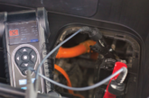

Lucas Assimos, an automotive specialist and independent workshop operator based in Florida, provides his top advice for fellow mechanics working with wiring problems.
A circuit can show a healthy-looking voltage on a multimeter and still be incapable of doing its job.
That is one of the simplest electrical lessons in the workshop, but it is also one of the easiest to forget when a vehicle arrives with several warning lamps, communication faults or a control unit that appears to be dead.
The trap is treating voltage present as proof that the circuit is healthy.
A digital multimeter places very little load on the circuit. That is useful for many checks, but it also means a damaged feed or earth path can sometimes show close to battery voltage while almost no current is flowing. As soon as the starter motor turns, a relay closes, a module wakes up or a motor begins to operate, the same circuit may collapse.
That difference between static voltage and voltage under load is where many difficult electrical diagnoses begin.
Start with the condition that creates the fault: If the complaint happens during cranking, test during cranking. If it happens when a high-current component operates, test while that component is operating. If a control unit drops offline during wake-up, observe the supply and earth at that moment. A key-off battery reading is useful, but it does not tell you what the electrical system is doing when demand rises.
I have seen vehicles with several apparently unrelated faults where the useful clue was not the individual fault-code description but the moment they appeared. A weak connection, poor earth or unstable battery supply can disturb several control units at once. The result may look like multiple failures when the original problem is shared power quality.
That is why I like to establish the electrical baseline before condemning expensive electronic components.
Voltage drop tells you what the circuit loses
For a loaded circuit, voltage-drop testing is often more useful than simply asking whether voltage is present.
Instead of measuring from the feed to earth and seeing 12 volts, measure across the part of the circuit you are questioning while current is flowing. A healthy cable, connection or earth path should lose very little voltage. If a meaningful amount appears across a connection or section of cable, that voltage is being lost before it reaches the load.
The exact acceptable value depends on the circuit, the manufacturer and the current involved, so I avoid treating one universal number as a rule for every vehicle. The important point is to compare the reading with service information, the opposite side of the circuit where appropriate, and the conditions under which the fault actually occurs.
On a starter circuit, for example, a connection that looks perfect with the engine stopped can become obvious once cranking current flows. The same principle applies on a smaller scale to module feeds, relay contacts, fan circuits and other loads.
Do not forget the earth side
Technicians naturally look for missing positive supply, but an unstable earth can create very similar symptoms.
Engine or body earth straps may have been disturbed during previous work. Corrosion can develop between an eyelet and the body. A terminal can be tight enough to look correct but still develop resistance under load.
Testing only continuity with the circuit switched off can miss this. The circuit may technically be connected, but that does not prove it can carry current without excessive voltage loss.
If several systems share an earth point, one poor connection can create symptoms across systems that appear unrelated on the scan tool.
Low-voltage history matters
Another question I ask early is whether the vehicle recently had a flat battery, slow crank, jump-start or charging-system problem.
Modern vehicles can record a large number of faults during a low-voltage event. Modules may reset at different points, communication can be interrupted, and sensor values may become implausible while supply voltage is unstable.
That does not mean every stored fault should be blamed on the battery. It means the event belongs in the diagnostic history.
Before clearing everything, I prefer to look at the fault pattern across the vehicle. If many modules recorded voltage or communication complaints around the same event, that pattern may be more informative than one isolated code.
Once stable voltage is restored, the next step is to determine which faults return under normal conditions.
Load the circuit before replacing the component
If a module has the correct feed voltage with the connector disconnected, that result alone is not enough for me to condemn the module.
The circuit needs to prove it can support the load. Depending on the circuit and the test procedure, that may mean back-probing under operation, carrying out a manufacturer-specified load test, using a suitable test load, or measuring voltage drop while the component is commanded on.
The method matters because inappropriate loading can damage sensitive circuits. The objective is not to force current through every wire. It is to test the circuit in a way that reflects the load it is designed to carry.
This is especially important before replacing an ECU or another costly controller. A new control unit connected to the same weak feed or poor earth will not repair the original problem.
Build the baseline first
When an electronic fault looks complicated, the most useful first steps are often basic ones: Confirm battery condition and system voltage under the condition that produces the fault. Verify the main feeds and earths under load. Look at voltage drop, not only static voltage. Review the full vehicle fault pattern before clearing it. Then decide whether the evidence still points to the control unit, sensor or network component.
The lesson is simple: A multimeter showing 12 volts can tell you that electrical potential is present. It does not automatically tell you that the circuit is capable of work. The circuit proves that only when the load arrives.