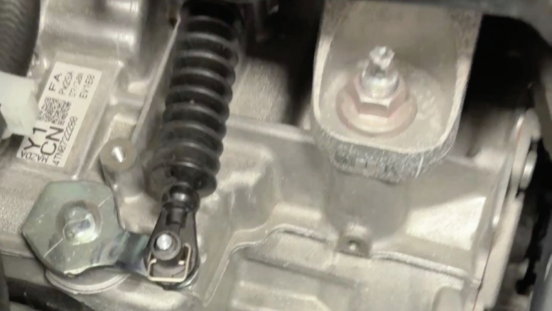
PMM’s wire-chaser Ben Johnson has been at it again recently with a particularly uncommunicative Mazda.
There are some diagnostic jobs where the fault practically introduces itself. A warning light comes on, the scan tool gives you a sensible code, you carry out a few tests, find a broken wire, replace the offending part and move on with your life. Then there are Mazdas.
The problem
This Mazda 3 arrived with a simple complaint: it would not start. No crank. No starter operation. Nothing. The instrument cluster displayed a rather unhelpful start-stop button fault message, which, in the great tradition of modern vehicle diagnostics, told me almost nothing of any use whatsoever.
Mazdas are particularly good at this sort of thing. They have a habit of throwing up vague starting-system warnings whenever they feel that something, somewhere, isn’t quite right. It might be a key issue. It might be an immobiliser fault. It might be a problem with the selector position. Or perhaps Saturn is in retrograde and the BCM simply isn’t in the mood. The most entertaining part was that there were no useful fault codes. Not one miserable little breadcrumb to point me in the right direction.
Finding the solution
So, as is often the case, the scan tool was politely put to one side and the multimeter came out. The starter relay was in the front fuse box in the engine bay. As with a conventional automotive relay, terminal 30 carried the main battery supply, while terminal 87 was the switched output towards the starter circuit.
Bridging terminals 30 and 87 operated the starter motor and, more importantly, the engine started (Fig. 2). That immediately ruled out a great many possibilities: The starter motor worked; the high-current circuit worked; the engine ran; the immobiliser was clearly not preventing the engine from operating once it had been cranked.
In other words, the problem was not downstream of the starter relay. The relay was simply not being commanded.
On the control side, terminal 86 received approximately 12 volts from the PCM during a start request. That voltage was present. Terminal 85, however, was supposed to be grounded by the Body Control Module. That ground was missing.
So now the question was no longer, why doesn’t the starter motor work? The real question was: why was the BCM refusing to switch it on?
Narrowing it down
The circuit also incorporated a monitor wire so that the PCM could supervise relay operation, because naturally, in a modern car, even a simple starter relay is no longer allowed to live a peaceful life without several control units watching it. But electrically, the situation was clear.
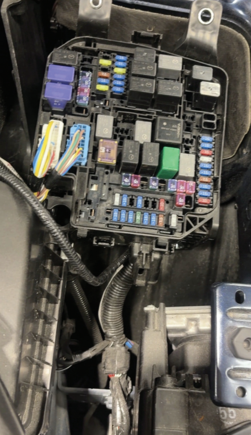
Fig 1 – A green starter motor relay seemed the best place to start.
Terminal 30: Battery voltage.
Terminal 86: 12 volts from the PCM
Terminal 85: No ground from the BCM and instead 12 useless Volts.
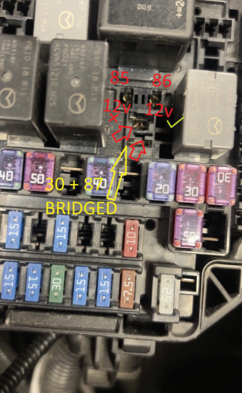
Fig 2 – The relay terminals 85 and 86 both had 12V present even when attempting to crank – smoking gun? I should be so lucky
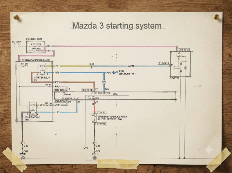
Fig 3 – Note terminals A and E on the wiring diagram. Tracing the brown wire back to the BCM we can see that the BCM grounds this wire when authorised and the blue wire on terminal E is energized with 12V with a monitoring line back to the BCM – very Mazda.
The BCM was deliberately inhibiting the start and now I just had to find out why. On any automatic vehicle with a no-crank complaint, one of the first obvious suspects is the transmission range information. The vehicle must know that the gearbox is in Park or Reverse. Drive showed Drive. Marvellous.
…Except the car still wouldn’t bloody start! Clearly the car knew something that the scan tool wasn’t showing me.
Totally wired
I went back to the wiring diagram and found there was one wire running from the automatic transmission to the Body Control Module. According to the wiring diagram, this was called the clutch inhibition switch circuit (Fig. 4). Immediately I wrote it off as irrelevant to the whole car. On the automatic transmission, this circuit was from the transmission to the BCM. That one wire told the BCM whether the gearbox was in a state where starting should be permitted. And this was the wire that was wrong. At the BCM, it was a red wire and I measured it at 12V. I moved the selector, still 12. I went through Park, Neutral, Reverse and Drive: all measured 12V. Suspicions raised, but still not the smoking gun. So I did what, in my opinion, is still one of the most powerful diagnostic techniques available to any technician and found another car that did work. A known-good vehicle is often worth more than twenty pages of technical documentation.
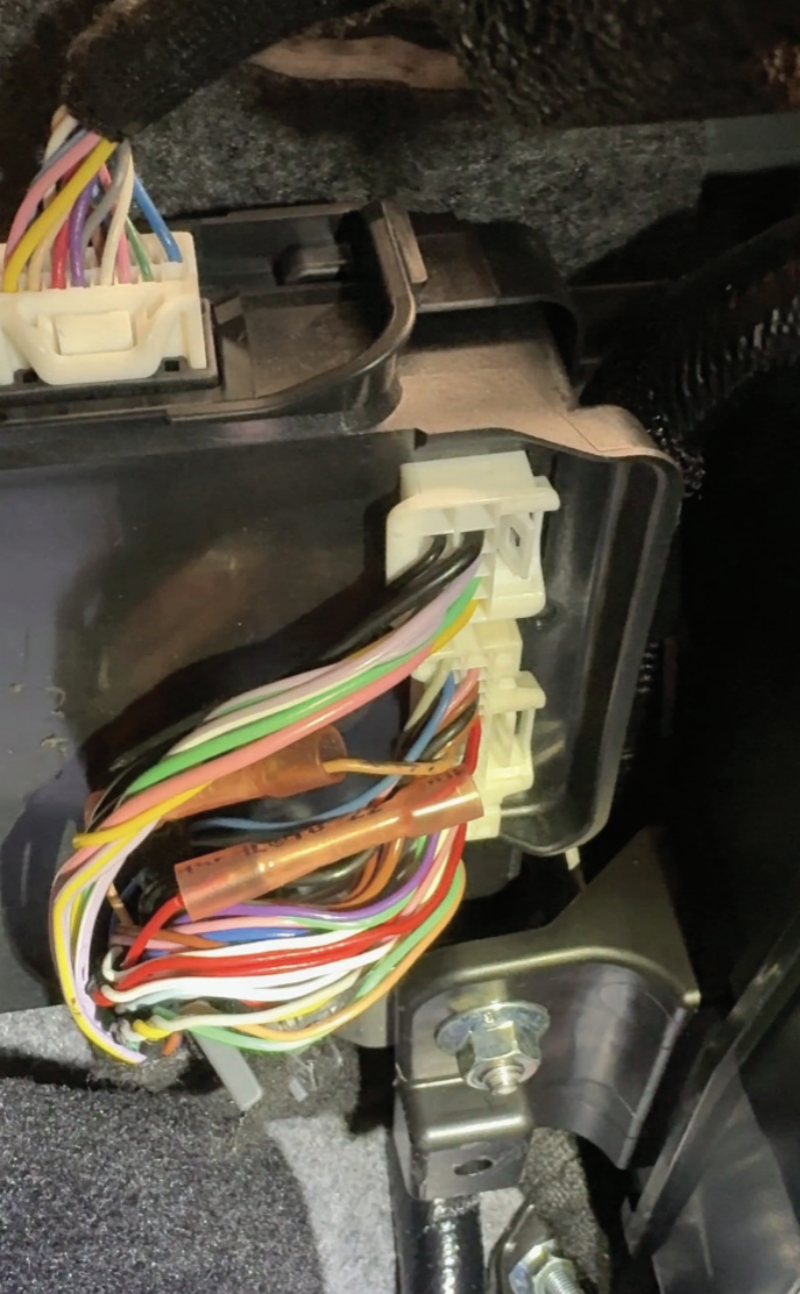
Fig 4 – The red wire here with the pink crimp connector is the feedback from what appeared to be a magneto resistive type sensor in the automatic transmission mechatronics – this was the real smoking gun.
Comparing with the healthy Mazda
On the known-good Mazda, the same yellow wire measured approximately 12 volts in Drive and Reverse, but in Park and Neutral, it dropped dramatically to approximately 186 millivolts. I thought to myself: Now we are getting somewhere. So, although the scan tool showed Park correctly, the dedicated starting-authorisation circuit to the BCM was still effectively saying: No. Do not start. Whilst the conventional live data said Park, the yellow wire disagreed and the BCM trusted the yellow wire. Which, frankly, was probably the sensible thing to do. The problem for the technician, of course, is that this important signal was not presented in the normal scan-tool live data.
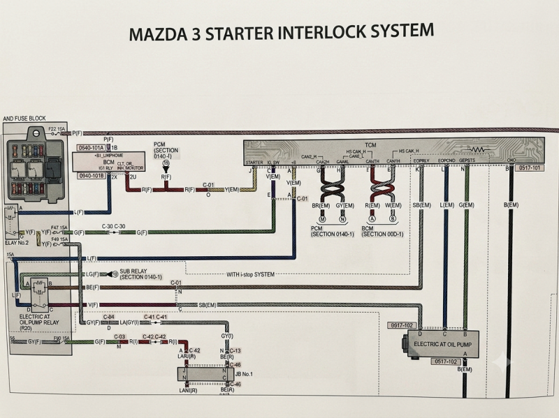
Fig 5 – Wire C-01 from the TCM terminal J to 2U on the BCM overview – note the yellow wire at the TCM. This was the affected circuit though from live data you never would have seen this as it is totally hidden and appeared to be private data for the BCM only… Hpw very wonderfully pointless
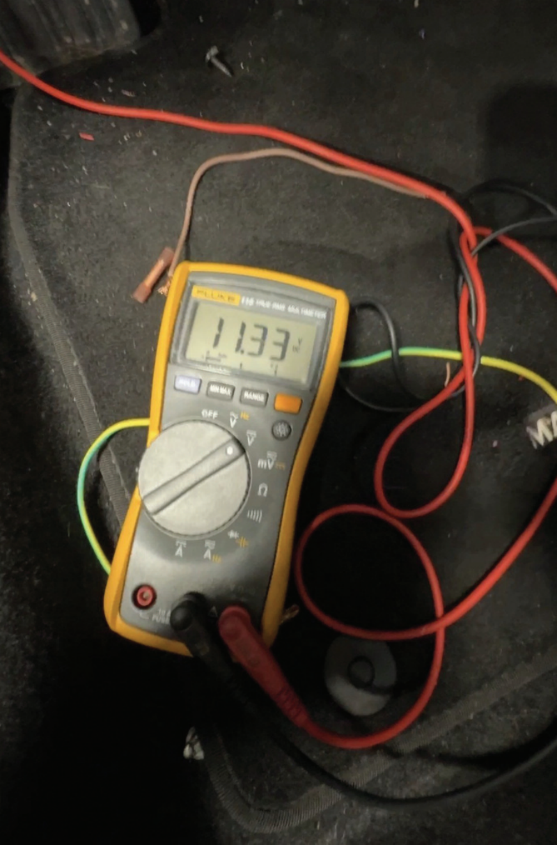
Fig 6 – In park, neutral, reverse or drive we had a constant 12V with no pull down to 185 mV – how very disappointing and frustrating. I only found out the correct values by comparing another car
Replicating the low voltage
Before replacing anything, I wanted to push the diagnosis a little further. I had an idea to simply create the correct voltage myself. I cut the red BCM wire and built a small pull-down circuit using resistors and Ohm’s law in an attempt to drag the voltage down to the same level as the known-good car. I’m pleased to announce that it worked. For a time. I managed to bring the signal down, but then the circuit dragged itself back up to around 1V and the car still refused to start.
This is something I have noticed with Mazdas before: They are extremely difficult to fool. You can try to jump or wire trick an old car with a sufficiently determined expression. Mazdas, however, will often look at that approach and say, Nice try, I see you.
The circuit may have involved an internal voltage divider, pull-up resistance, current monitoring or some other plausibility strategy. The exact internal electronics were less important at this stage than the evidence already sitting in front of me.
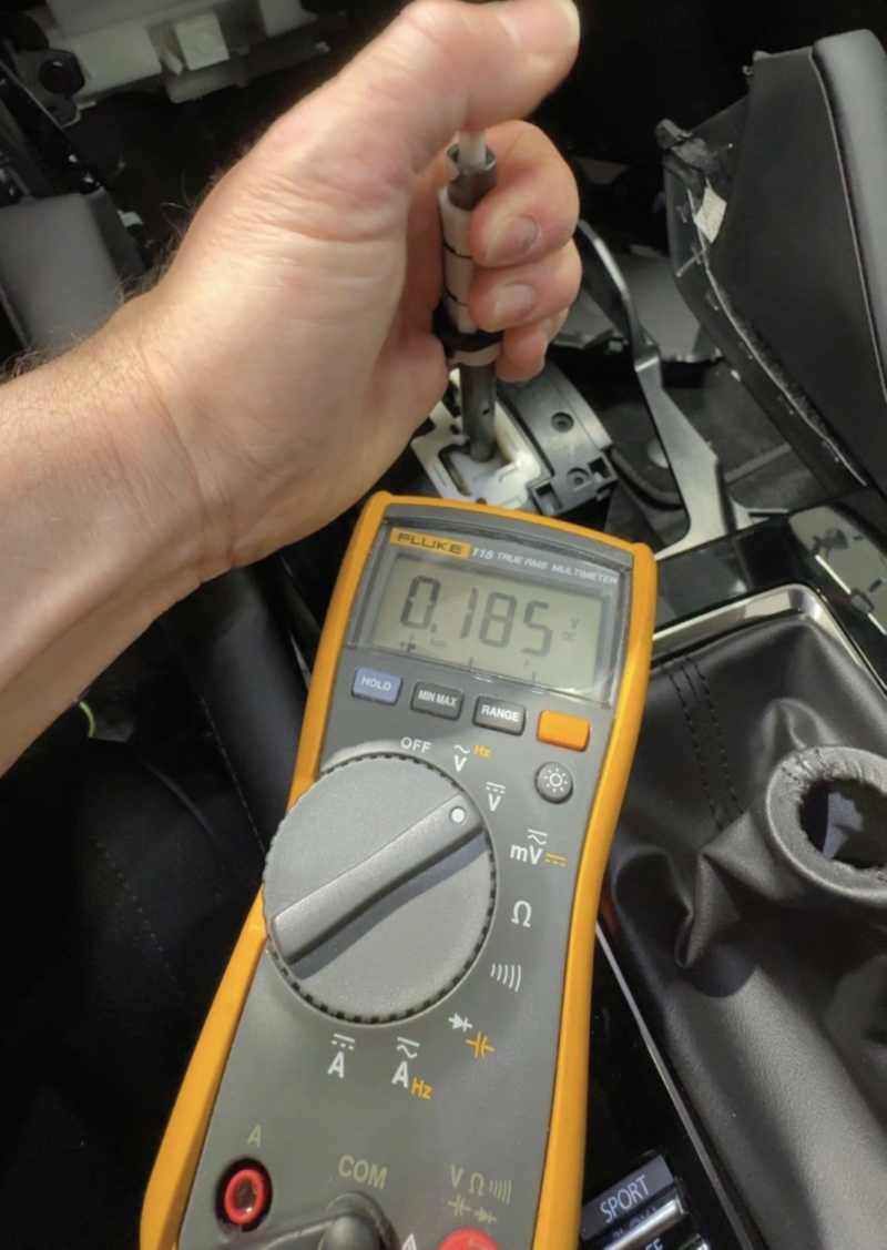
Fig 7 – The new mechatronics installed and the wonderfully elusive 185 mV was finally present in park and neutral. In drive and reverse we had 12V
The known-good car produced approximately 186 millivolts in Park and Neutral. The wiring diagram showed 12 volts for the direct transmission-to-BCM starting authorisation circuit. The BCM was withholding the starter relay ground. The starter motor and high-current circuit had already been proven good… There comes a point in diagnostics where further testing stops being diagnosis and starts becoming an argument with the car and I’d had enough.
Inside the transmission
The fault was eventually traced to the transmission valve body assembly. As the contact position detection, but the practical result was what mattered.
That internal assembly was responsible for generating the authorisation signal sent along the yellow wire to the BCM and it was getting it wrong.
I replaced the valve body and then came the moment of truth:
-
In Drive: approximately 12 volts.
-
In Reverse: approximately 12 volts.
-
In Neutral: approximately 186 millivolts.
-
In Park: approximately 186 millivolts.
The starter relay was now authorised. Mazda got the better of me for a while, but finally, the job was done.
Don’t rely on the scan tool
Jobs like this prove why electrical testing still matters. A scan tool can show you a great deal, but at the end of the day it only shows you the information the manufacturer has chosen to make available.
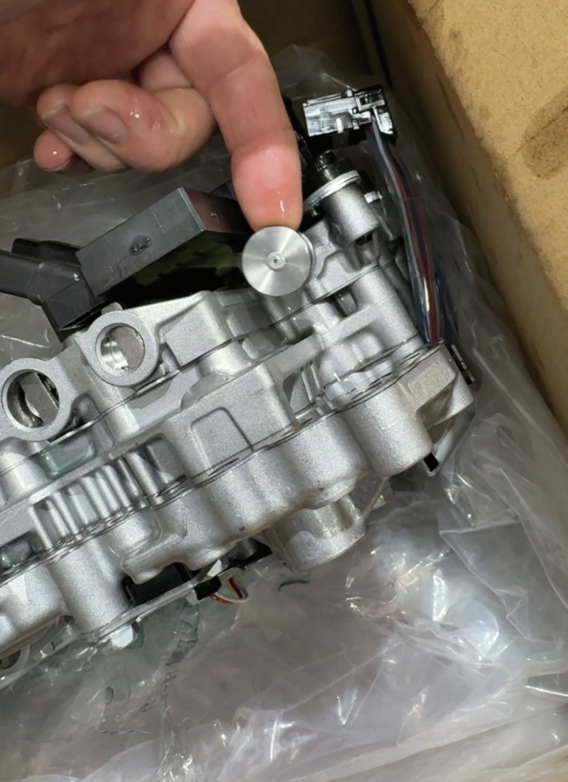
Fig 8 – Note the yellow sliding element next to my finger inside the casing. The external selector shaft pulls the circular sliding element in and out thus changing the value of the sensor inside the mechatronics. Clearly the sensor had failed
Sometimes the most important signal on the entire vehicle is the one you cannot see in live data and in this case, it was one yellow wire. Once that wire finally dropped from 12 volts to 186 millivolts, the Mazda started as though nothing had ever happened.
Which is always the final insult. Hours of testing, wiring diagrams, resistors, and guesswork… and then it just starts normally, as if to say, “What took you so long!”