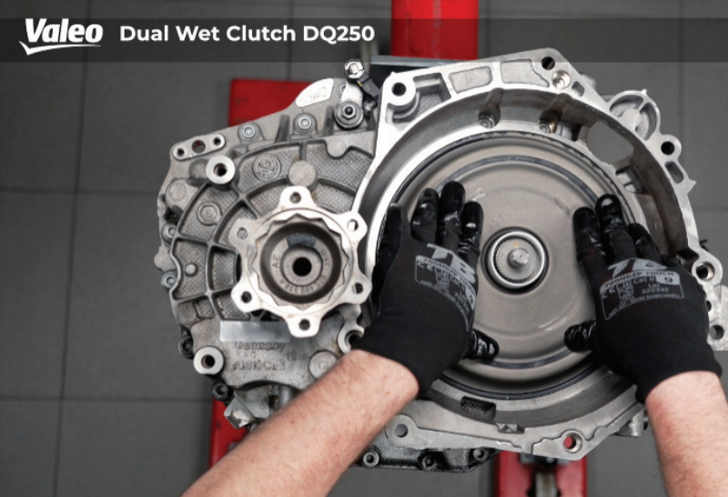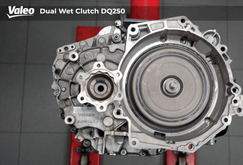
Valeo guides readers through a clutch replacement.
Pre-diagnostic checks
Non-invasive checks first: Always check dual clutch transmission fluid (DCTF) level and quality before disassembling. Degraded fluid causes mechatronic valve scoring, solenoid sticking, and pressure loss.
Dismounting
Step 1
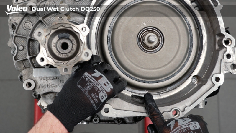
Snap ring removal: Utilise a flat-head instrument to extract the snap ring from the clutch housing end cap with precision.
Step 2
Clutch cap detachment: Carefully lever the clutch end cap away from the housing using a suitable flat-head tool.
Step 3
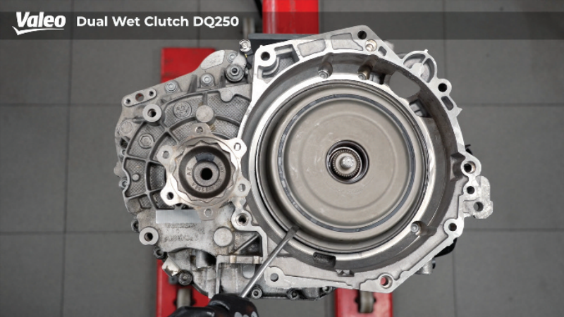
Snap ring inspection: Identify the snap ring and perform a visual check for any signs of structural damage or abnormal deformation.
Step 4
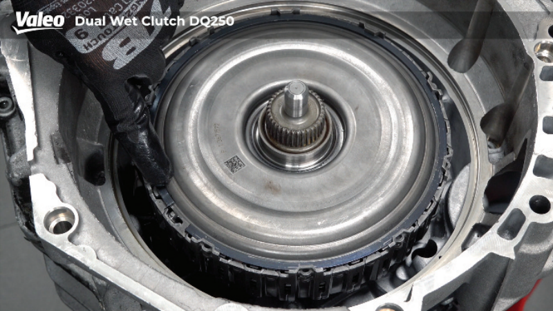
Alignment verification: Confirm that reference marks on the driving disk and external plate carrier are clearly discernible; if they are absent, manually apply them before continuing with disassembly.
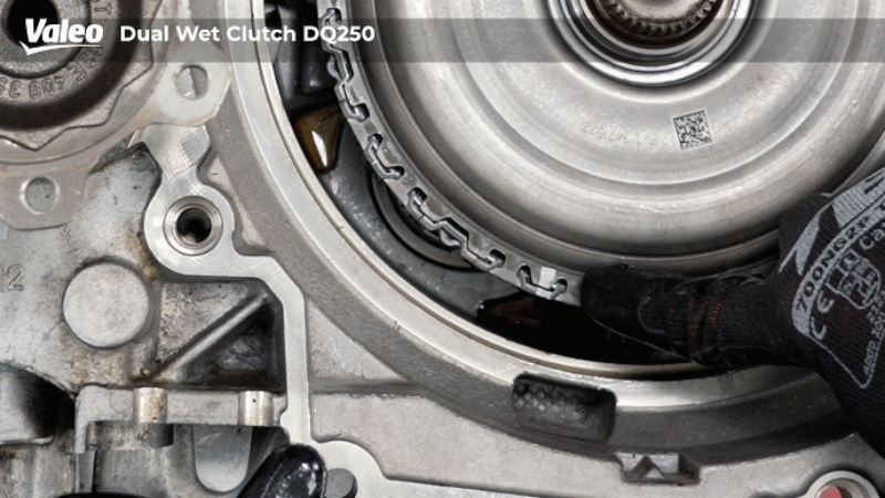
Step 5
Component extraction: Using a flat-head instrument, meticulously remove the snap ring from the driving disk assembly.
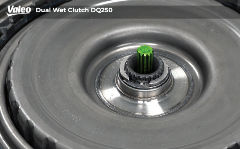
Step 6
Oil pump extraction: Withdraw the shaft from the ATF oil pump assembly with care.
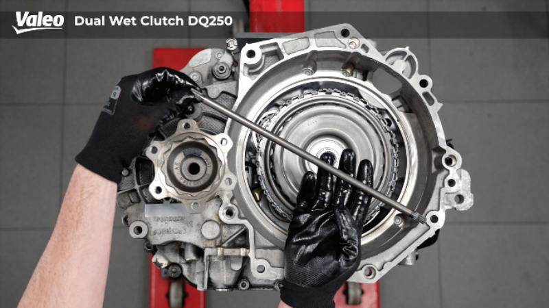
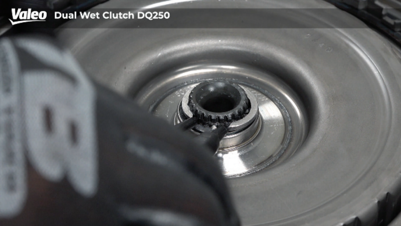
Step 7
Remove the snap ring.
Step 8
Hook installation: Attach and fasten the specialised mounting hooks to either side of the component, ensuring they are perfectly centred relative to the double clutch assembly.
Clutch removal: Carefully lift the double clutch. clutch unit upward to extract it from the housing.
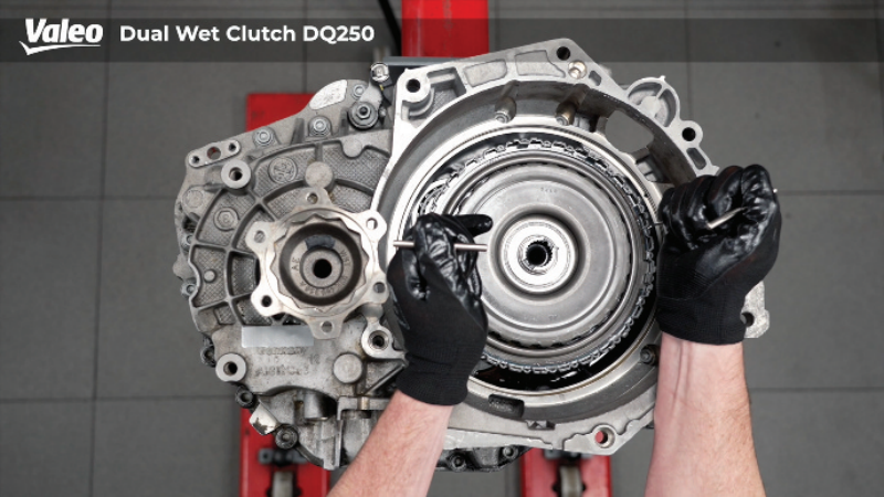
Step 9
Flange surface inspection: Inspect the transmission flange running surface thoroughly for any indications of operational wear.
Structural integrity check: Verify the absence of scoring, grooves, or surface irregularities on the component face.
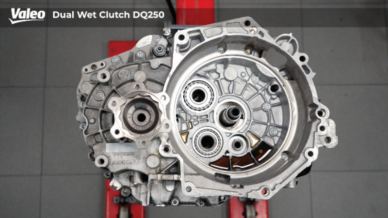
Fitting process
Step 10
Seal inspection: Verify the mobility of all hub sealing rings by rotating them manually; they must move freely without any resistance or mechanical binding.
System architecture: Contrasting with dry configurations, the 02E utilises dual concentric multi-plate packs (k1 and k2) submerged in fluid to enhance thermal dissipation and facilitate seamless torque modulation.
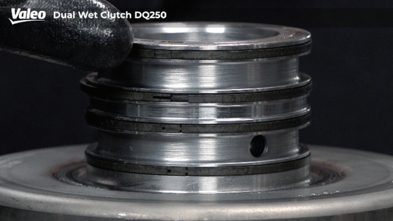
Sealing ring staggering protocol
Step 11
Primary alignment: Ensure the openings for sealing rings 1 and 3 are perfectly aligned in the same position.
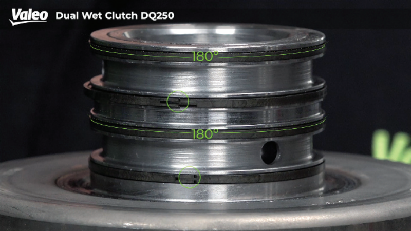
Secondary offset: Position the gaps for sealing rings 2 and 4 at a precise $180^\circ$ rotation relative to the first and third rings.
Technical requirement: Proper staggering is vital for maintaining hydraulic integrity; misaligned gaps allow high-pressure fluid bypass, which triggers clutch slippage, excessive thermal generation, and catastrophic friction degradation.
Transmission housing clutch integration
Step 12
Component installation: Meticulously descend the double clutch unit onto the transmission input shaft assembly.
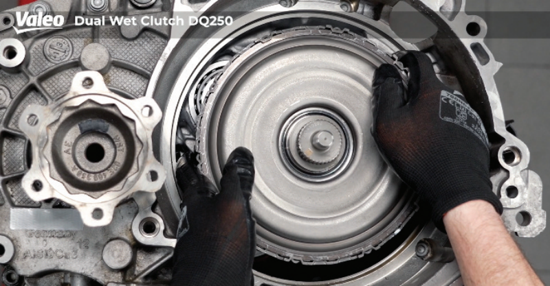
Step 13
Spline engagement: Should the splines fail to mesh, partially elevate the unit and rotate it before reattempting; avoid applying excessive force or allowing the component to drop.
Technical requirement: Forcing a poorly seated unit will irreparably damage internal shaft seals and spline surfaces; such mechanical negligence will result in immediate warranty invalidation.
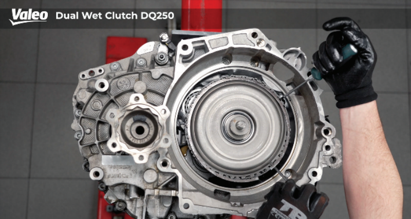
Step 14
Alignment validation: Confirm that the reference indicators on the driving disk and outer plate carrier are clearly perceptible and correctly oriented.
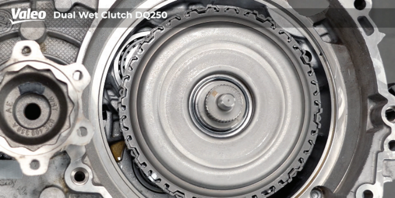
Step 15
Cap detachment: Meticulously lever the assembly cover away using a flat-head instrument to reveal the internal retaining ring channel.
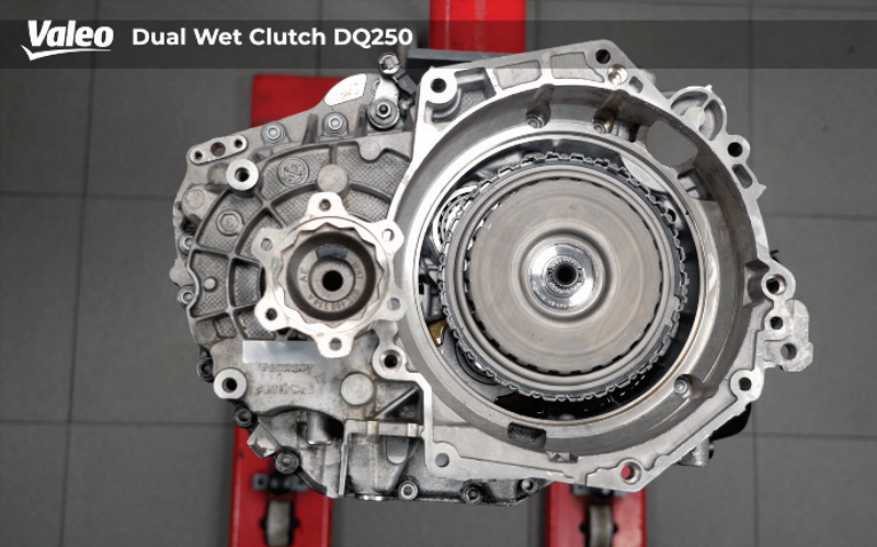
Step 16
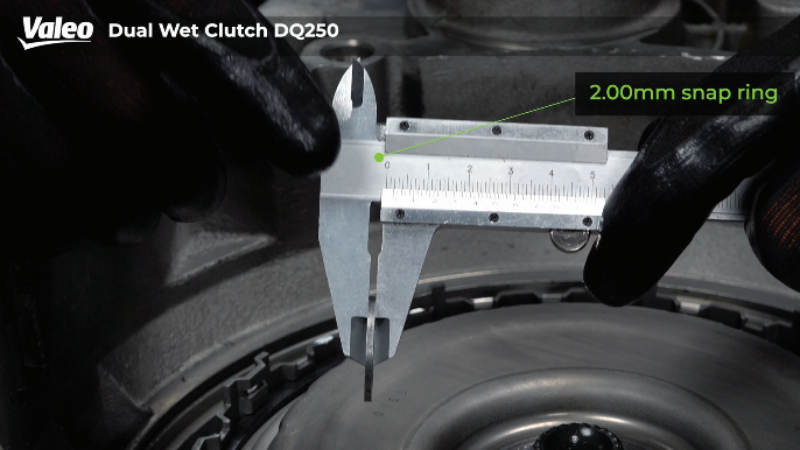
Shim selection: Retrieve the 2mm calibration washer from the supplied kit and seat it precisely onto the primary shaft assembly.
Step 17
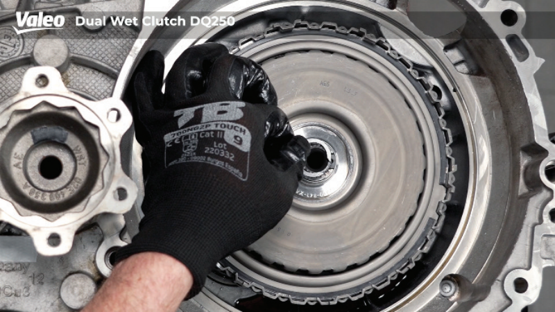
Axial clearance base setup: Secure the preliminary 2mm snap ring within its channel to define the requisite zero-point reference for subsequent axial clearance calibration.
Axial clearance calibration protocol
Steps 18 & 19
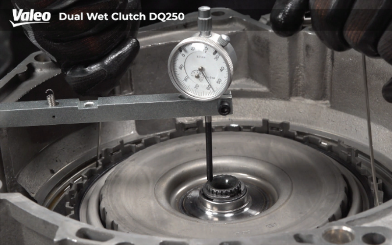
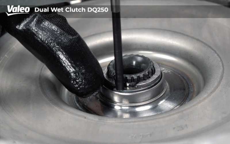
Primary shaft verification: Configure a dial gauge to execute measurement 1, determining the specific axial play of the transmission input shaft assembly.
Step 20
Clutch play assessment: Utilising mounting hooks, elevate the external clutch carrier vertically, ensuring zero lateral tilt, to Valeo Dual Wet Clutch DQ250 establish measurement 2 (axial clearance relative to the shaft).
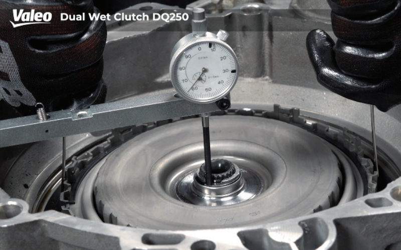
Step 21
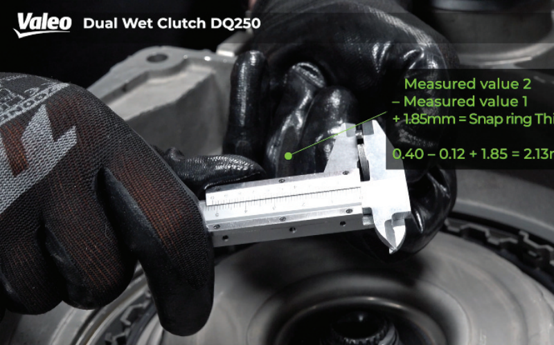
Calibration computation: Establish the requisite thickness for the shim or retaining ring by executing the following axial clearance calculation: Measurement 2 – Measurement 1 + 1.85mm = requisite snap ring thickness.
Technical requirement: If the computed result lies between available increments, increment to the subsequent larger Valeo Dual Wet Clutch DQ250 dimension. Precise axial clearance calibration is vital; the mechatronic controller depends on exact stroke tolerances to perform critical self-adaptation and clutch engagement learning protocols.
Step 22
Final ring installation: Extract the preliminary 2mm setup ring and meticulously install the specific snap ring derived from your calibration calculations.
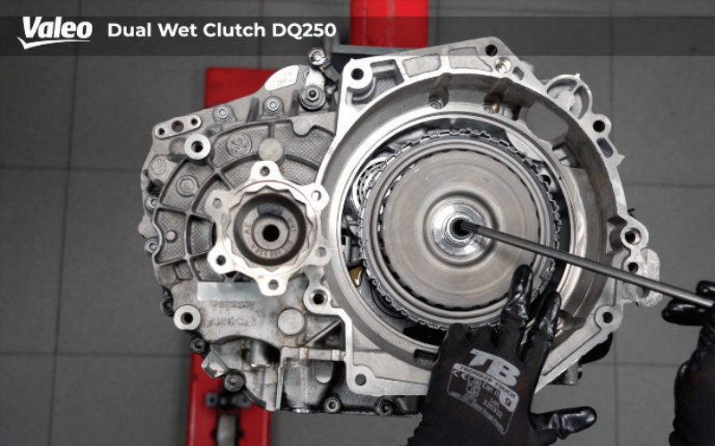
Step 23
Seating verification: Confirm the snap ring is fully seated within the groove channel across its entire circumference; it must remain stationary and exhibit no rotation or vertical movement.
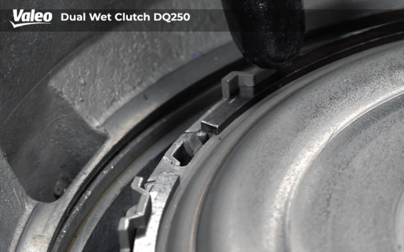
Steps 24 & 25
Housing integration: Orient the clutch end cap horizontally relative to the sleeve assembly.
Component seating: Apply uniform manual pressure to the component until it is fully engaged within its respective housing channel.
Technical requirement: Refrain from utilising hammers or prying implements on the clutch end cap. Applying disproportionate force will compromise the component’s structural integrity, resulting in severe lubricant leakage. Insufficient dual clutch transmission fluid (DCTF) levels trigger fluid aeration and cavitation, culminating in a total failure of system hydraulic pressure.