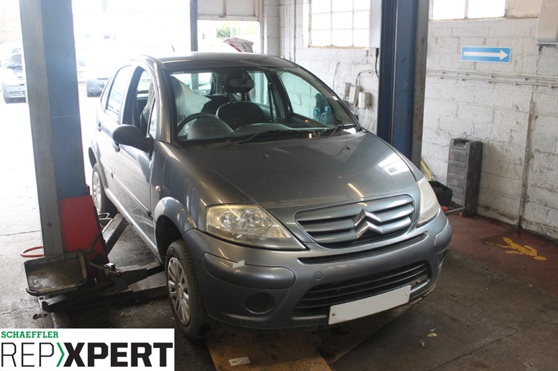
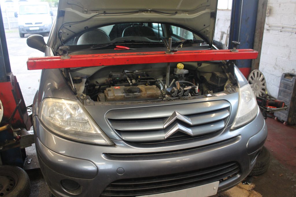
This month, REPXPERT’s Alistair Mason replaced the clutch on a 2005 Citroën C3 fitted with a 1.4L (TU3A) petrol engine. Whilst the car was in for a routine service, the garage noticed the bite point of the clutch was very high and advised replacing the clutch.
The Citroën C3 was launched in April 2002, replacing the Saxo. Being part of the PSA group, it shared he same chassis as the Peugeot 1007 and 207 and also some components with the 206, so when opening the bonnet, things may look quite familiar.
Step-by-step procedure
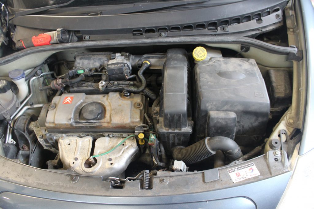
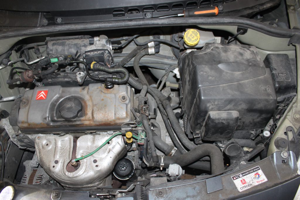
With the car positioned on the ramp, open the bonnet (see above), disconnect the top engine breather pipe and remove the air filter assembly (see below), then remove the battery covers, unclip and remove the control unit, which can then be stowed at the front of the engine bay.
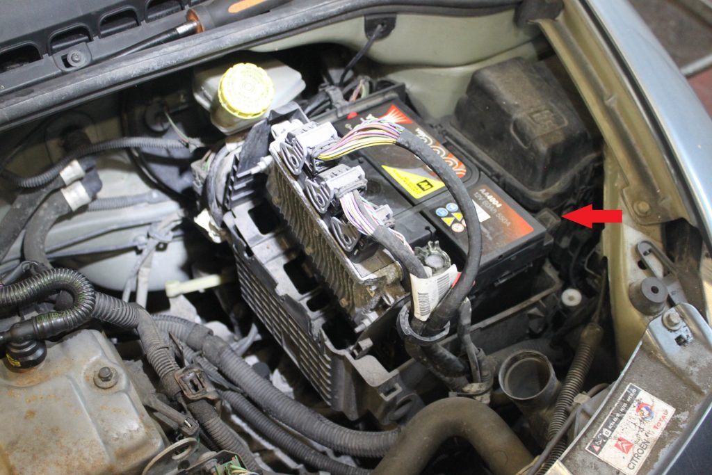
Disconnect the battery and remove it from the tray by releasing the retaining clip (see below), then disconnect the multi-plugs from the control unit at the back of the battery box. Note – the main multi-plug has a small ‘R’ clip retaining the release clip that has to be removed before the release clip can be removed.

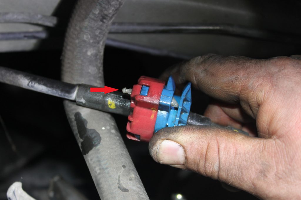
The battery tray can then be unbolted and removed with the control unit (see above). Now remove the gear change cable by disconnecting the ball joint from the selector arm and then, pulling back the white pin (see below) on the outer cable, remove it from the bracket. The cable can then be stowed in the bulkhead area.
With the vehicle still on the ground, slacken both front hub nuts and then raise the ramp to gain access to the underside and drain the gearbox oil, as the driveshafts have to be removed. Whilst the oil is draining, lower the vehicle to waist height and remove both front wheels and both front hub nuts, then the pinch bolts for the bottom ball joints and disconnect the front hubs from the bottom arms by levering down on the bottom arms. Pull the hub assemblies out and remove the driveshafts from the hubs, which can then be pulled/levered out of the gearbox and fully removed from the vehicle. Remove the N/S/F wheel arch liner as this gives good access to the gearbox.
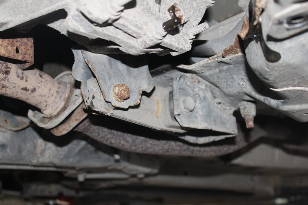
Raise the vehicle to gain access to the underside. Remove the front sub frame brace bar, the gearbox rear pendulum mounting (see above) and the two clutch slave cylinder retaining bolts and stow the clutch slave cylinder assembly.
Disconnect the engine speed/position sensor from the front of the bell housing, and then unclip the wiring loom and stow safely, as this can be damaged when removing the gearbox. Now remove the starter motor mounting and lower bell housing bolts. The starter motor will stay in position, but leave the bell housing bolt positioned at nine o’clock in place, as this will retain the gearbox until it is ready for removal. Lower the vehicle to ground level and remove the gearbox earth lead, reversing light switch multi-plug and the upper bell housing bolts. Using an engine brace to support the engine (see below), remove the gearbox mounting and then lower the engine on the engine brace.
Raise the vehicle to gain access to the underside, support the gearbox with a transmission jack, remove the final bell housing bolt left in the nine o’clock position and ease the gearbox away from the engine. When the gearbox is free from the clutch, lower the transmission jack and remove the gearbox. The clutch can now be unbolted and removed from the flywheel.
On inspection of this example, the friction material had worn closely to the retaining rivets, indicating that the clutch was close to the end of its service life and required replacing. Carry out a visual inspection of the clutch area for any oil or coolant leaks that could contaminate the new clutch and inspect the flywheel for any ‘blueing’ or cracks from excess heat and replace if required. If in good condition, remove the ‘glaze’ from the flywheel surface with some emery cloth. Now inspect the gearbox bell housing for any oil leaks and remove the old release bearing and fork. Check all the pivot points and release the bearing sleeve for any wear, replacing if required. Clean the bell housing to remove the clutch dust and it the release fork, applying a light smear of high melting point grease to the pivot points and fit the new release bearing.
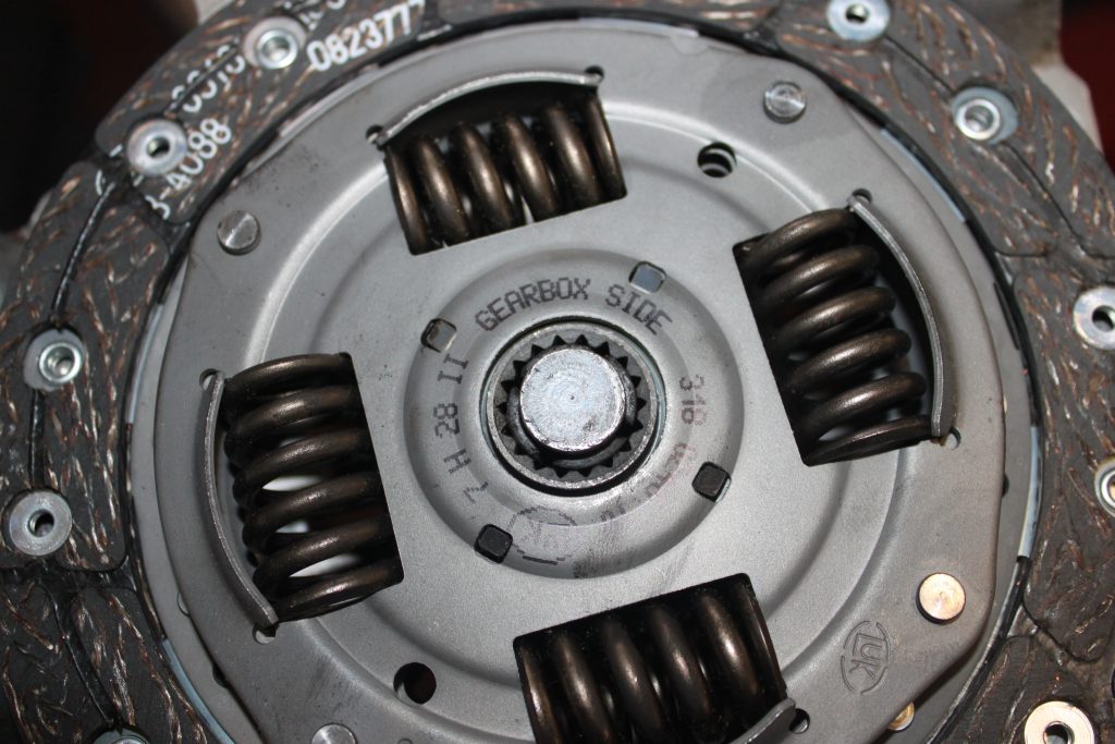
Apply a light smear of high melting point grease to the gearbox input shaft splines and then slide the new clutch plate onto the input shaft. This will ensure it has the correct clutch plate prior to installing the gearbox and it will also evenly distribute the grease. Next, remove the clutch plate and wipe off any excess grease. Fit the new clutch to the flywheel using a clutch alignment tool and ensure the clutch plate is installed correctly with “Gearbox side” facing outwards (see below) and tighten the clutch bolts in an even and sequential manner.
Before installing the gearbox, check the two gearbox alignment dowels are still located in the engine. Then, using the transmission jack, install the gearbox carefully and once located on the dowels, refit in reverse order of removal, remembering to refill the gearbox with the correct quantity and quality of oil. When the battery has been installed, reset all electrical items as required and always road test the vehicle to ensure the repair is completed successfully.


