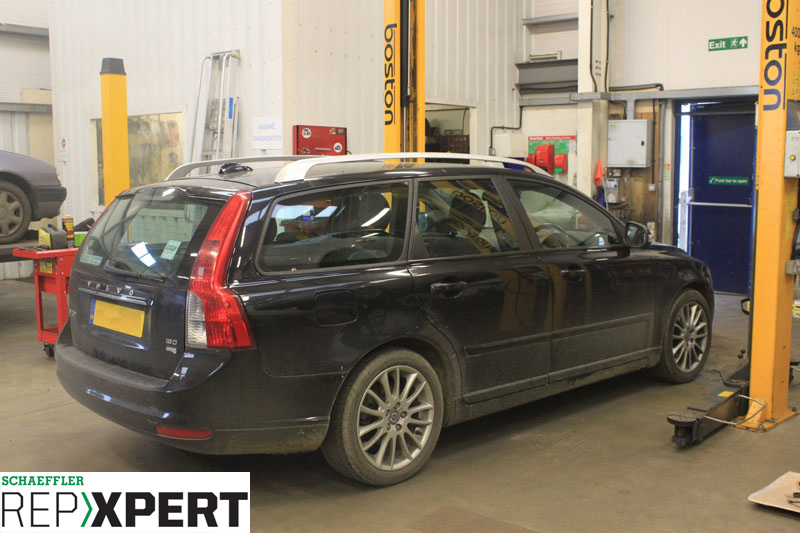
This month, REPXPERT’s Alistair Mason replaced the clutch on a 2010 Volvo V50, which was fitted with a 1.6 turbo diesel engine, had covered slightly less than 160,000 miles and reportedly suffered from clutch ‘slipping’. Volvo added the V50 to its range in 2004 and the vehicle shares the same platform as the Ford Focus.
Step-by-step procedure
With the vehicle placed on the ramp, open the bonnet (see below).

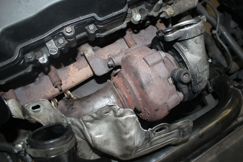
Remove the battery cover, detach the diesel particulate filter (DPF) pressure sensor, disconnect and remove the battery, remove the battery carrier, remove he plastic engine cover and then disconnect and remove the air filter assembly. This engine is fitted with a DPF, which needs to be lowered to access one of the front bell housing bolts. Disconnect the DPF at the turbocharger by removing the air intake hose, heat shield and retaining clamp (see below).
The DPF can then be eased down to give clearance. Whilst in the engine bay, disconnect the gear change cables by easing the ball joints apart and unclipping the outer cable. Clamp the hydraulic clutch feed pipe, then disconnect it from the concentric slave cylinder (CSC) by releasing the retaining clip and stow in the bulkhead area.
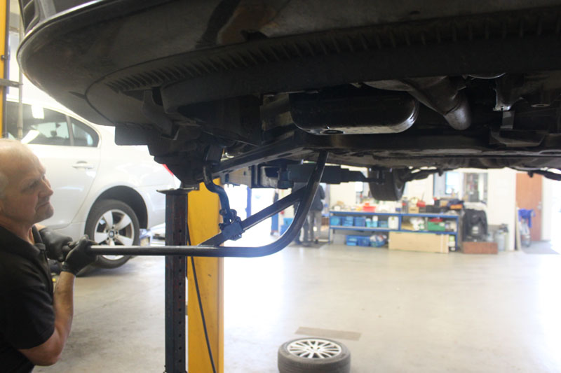
Ease the engine wiring loom back from the bell housing area to gain access to the top bell housing bolts and then remove these bolts. Before raising the ramp, slacken both front locking wheel bolts and both front hub nuts. Raise the ramp to waist height, remove both front wheels and the O/S/F wheel arch liner, then raise the ramp to access the underside of the vehicle – remove the engine under tray if one is fitted – and then drain the gearbox oil (see below).
Release both front bottom ball joints and disconnect from the hub assemblies (see below). The outer driveshaft joints will now ease out of the hub assemblies, and the N/S driveshaft will lever out of the gearbox.
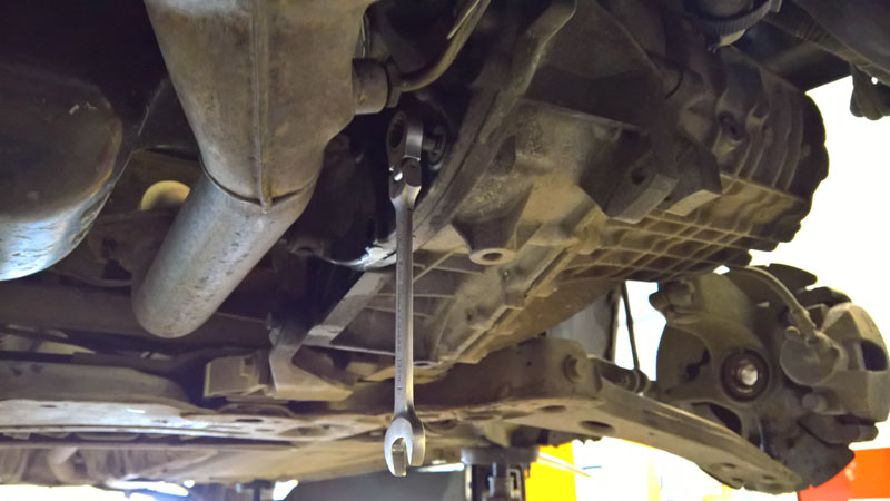
On the O/S driveshaft, unbolt the centre bearing from the back of the engine block (see below) and then lever out of the gearbox.
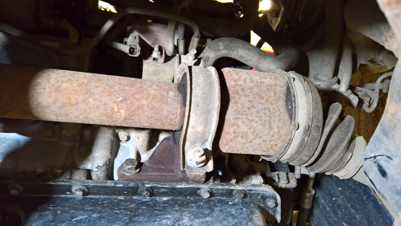
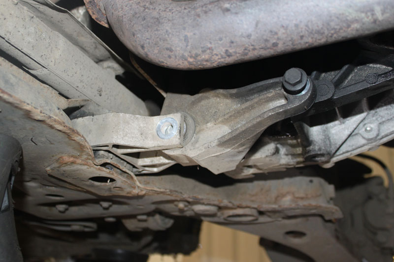
Remove the vacuum unit, which is attached to the starter motor, and then detach the three bolts that old the starter motor to the bell housing, the gearbox torque mount (see below) and the lower bell housing bolts.
Leave the two bell housing bolts located at 3 o’clock and 9 o’clock in position, as these will hold and support the gearbox prior to removal. Support the engine with a tall axle stand – alternative options include a subframe attached engine support or an engine brace bar attached from above – and support the weight of the engine. Remove the complete gearbox top mounting for more clearance when removing, support the gearbox with a transmission jack and then remove the final two bell housing bolts positioned at 3 o’clock and 9 o’clock. Next, slightly lower the engine and ease the gearbox away from the engine and lower when clear.
With the gearbox removed, detach the clutch assembly from the flywheel. On this occasion, with the clutch removed, it was clear to see that it had reached the end of its service life; the friction material had worn level with the lining rivets.
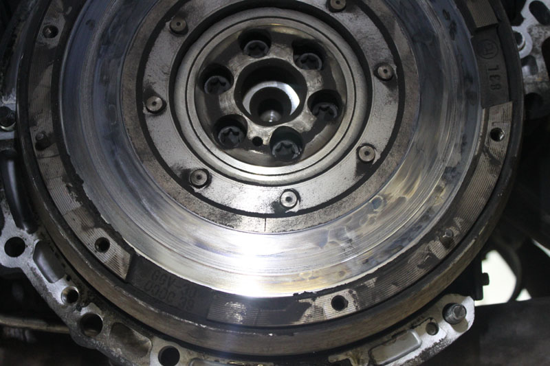
Inspect the dual mass flywheel (DMF). In this instance, wear marks from the rivets were present and there was evidence of excess heat as the surface was ‘blued’ (see below), so the flywheel had to be replaced.
With the old flywheel removed, check the back of the engine for oil or coolant leaks, to ensure there is no risk of contamination to the new clutch – this time, the rear main oil seal had to be repaired.
Fit the new DMF. To ensure the correct location, replace the bolts and torque to the correct tightness, as advised by Schaeffler’s DMF Checkpoint app. Using brake and clutch dust cleaner, remove all the clutch dust from the bell housing, before removing the old CSC and ensuring the mounting surface for the new CSC is clean.
When taking the new CSC from its packaging, keep an eye out for two technical bulletins which will be attached; one will advise to discard the original CSC fixing bolts, while the other will instruct to confirm that the seal has been removed and that a bead of sealer has been applied correctly to the new CSC. These bulletins are also linked to the clutch kit on REPXPERT.
When fitting the new CSC, do not squeeze the cylinder, as this can cause internal damage. Also, when fitting it to the gearbox, take care not to damage the gearbox input shaft seal located in the new CSC. Once in position, fit the new bolts and torque to the manufacturer’s specification. Smear a small amount of high-melting point grease on the splines of the input shaft, and slide the new clutch plate onto the input shaft. This will evenly distribute the grease on the splines and ensure the spline fitment is correct. Next, remove the clutch plate and wipe off any excess grease.
Fit the new clutch to the DMF. The new clutch being fitted during this repair was the latest design in self-adjusting clutches (see below).
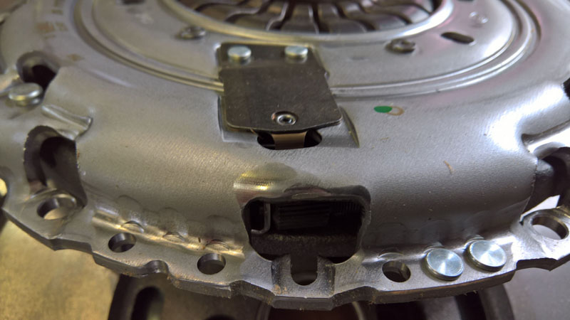
This type of clutch can be identified by the square sprung steel plate, which controls the adjuster wheel. In addition, it features a travel-controlled adjustment, opposed to the original design which has load-controlled adjustment and can be identified by the small yellow adjuster ring springs located on the front face of the clutch cover. It is strongly advised, when mounting a self-adjusting clutch, that you use the selfadjusting clutch mounting tool. Also ensure that the flywheel face is clean before mounting the clutch plate onto it. Ensure the clutch plate is fitted correctly, with either ‘Gearbox side’ or ‘Getriebe Seite’ stamped in the centre of the clutch plate and facing outwards, then locate the clutch pressure plate/cover and install into position correctly with the self-adjusting clutch tool (see below).
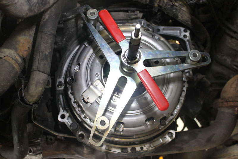
Once in position, secure with three bolts, remove the self-adjusting clutch tool, fit the remaining three bolts and torque to the manufacturer’s specification. Before refitting the gearbox, it is best practice to flush/change the clutch hydraulic fluid, which is achieved easily by placing a drain tray under the clutch pipe, removing the clamp and allowing the fluid to drain out. As the fluid drains, top up the reservoir as required until clean/new fluid is flowing through and then re-clamp. This will ensure that the new CSC and rubber seal will not become contaminated, which could cause a premature failure.
Check that the alignment dowels are located correctly in the engine block and re-fit the gearbox – taking time to ensure correct alignment and angle is achieved during installation. Once located on the dowels, re-fit in reverse order of removal. Once the gearbox is bolted to the engine and secured on the mounting, install the hydraulic clutch pipe and bleed the clutch as it is easily accessible. This particular CSC has a two-position clutch pipe connection, so locate the pipe on the first position. Subsequently, attach a bleed container and pipe to the nipple, remove the clamp and allow the fluid to run through. When all of the air has dispersed, push the pipe into the connection so it locates in position two. This will then shut off the bleed nipple, and the hydraulic system will operate correctly.
When the driveshafts have been fitted, remember to replace the gearbox oil with the correct quantity and specification of oil and after battery installation, reset electrical systems and control units as required.