The PicoScope is a well-known diagnostics tool, but when is the right time to use it? Pico Technology is here with a guide on how and when to use it for the best results.
Make no mistake, a PicoScope is not required for every diagnostic challenge! Like every tool at our disposal, there is a time and place to use a scope in the workshop. Knowing when and where to apply the scope will provide a return on investment within days, rather than years.
If we consider a typical diagnostic process, a sequence of 12 steps quickly generates considerable information and measurement data. This creates the evidence required to make an informed diagnosis or a request for additional diagnostic time (if economically viable).
- Correctly identify the vehicle
- Interview with the customer if possible to better understand the symptoms
- Verify the complaint (Not always possible)
- Use a scan tool to obtain DTCs and the parameter data
- Check for technical bulletins (software updates)
- Apply any initialisation or calibration routines if applicable
- Refer to the technical literature provided to acquire system description and operation
- List the possible causes
- Create an action plan based on accessibility and probability
- Apply the PicoScope initially (non-intrusively)
- Apply the PicoScope intrusively if required, based on the repair process
- Confirm the repair with the Scan tool and verify with the PicoScope
The above procedure is a guide, and those with superior product knowledge may shuffle the order above to bring about a rapid conclusion.
Assuming the vehicle under test is unknown to the technician, the steps above will return a conclusive diagnosis if adhered to.
Note how there is no mention of PicoScope until step 10, followed by the caveat “non-intrusively” as steps 1 to 9 may well conclude your diagnosis! However, should real-time analysis of the system under
test be required, it can only be actioned with a PicoScope.
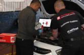
Let’s take a real-world example, from a vehicle that suffered with prolonged cranking and intermittently failed to start.
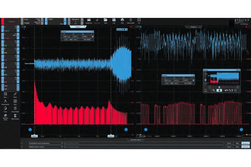
Steps 1 to 8 had failed to resolve the concern. Armed with an action plan (step 9), our crankshaft sensor signal and starter motor cranking current were monitored in real time during the fault condition. Referring to the split image above, in the left-hand image, the engine is cranking for over two seconds and the crankshaft signal appears distorted (blue waveform).
Referring to the image, we have zoomed into the crankshaft sensor signal to reveal excessive distortion. This is a result of the constant switching of the starter motor current (red waveform).
To cut a long story short, the high switching current (caused by poor commutator contact), resulted in the generation of electromagnetic interference (EMI). This corrupted the crankshaft sensor/wiring in close proximity to the starter motor.
The irony is that the customer had recently fitted a “new” starter motor, where the engine cranked as normal!
Armed with the above saved, dated, and time-stamped capture, we can present the customer with the evidence to prove that the “new” starter motor is faulty, even though it cranks the engine as normal. Such evidence can also be used with the supplier of the starter motor who in turn, can hand this back to the manufacturer for their warranty claim.
The above is one example where PicoScope fits during diagnosis (with minimal intrusion), but let’s not forget how the scope can also be used during routine maintenance to acquire signature waveforms. These can then be used to monitor adverse changes in component performance, avoiding potential failure and costly vehicle problems later. I guess that is why PicoScope has been nicknamed the Swiss Army Knife of diagnosis!


![Bosch’s ESI[tronic] diagnostic software](https://pmmonline.co.uk/wp-content/uploads/2026/03/Febi-diagnostics-tool-165x109.jpg)