Wayne McCluskey, Technical Training Manager at ZF Aftermarket, explains the straightforward 10-step procedure for replacing and coding the electrically powered hydraulic steering (EPHS) pump on a 2004-12 Ford Focus II.
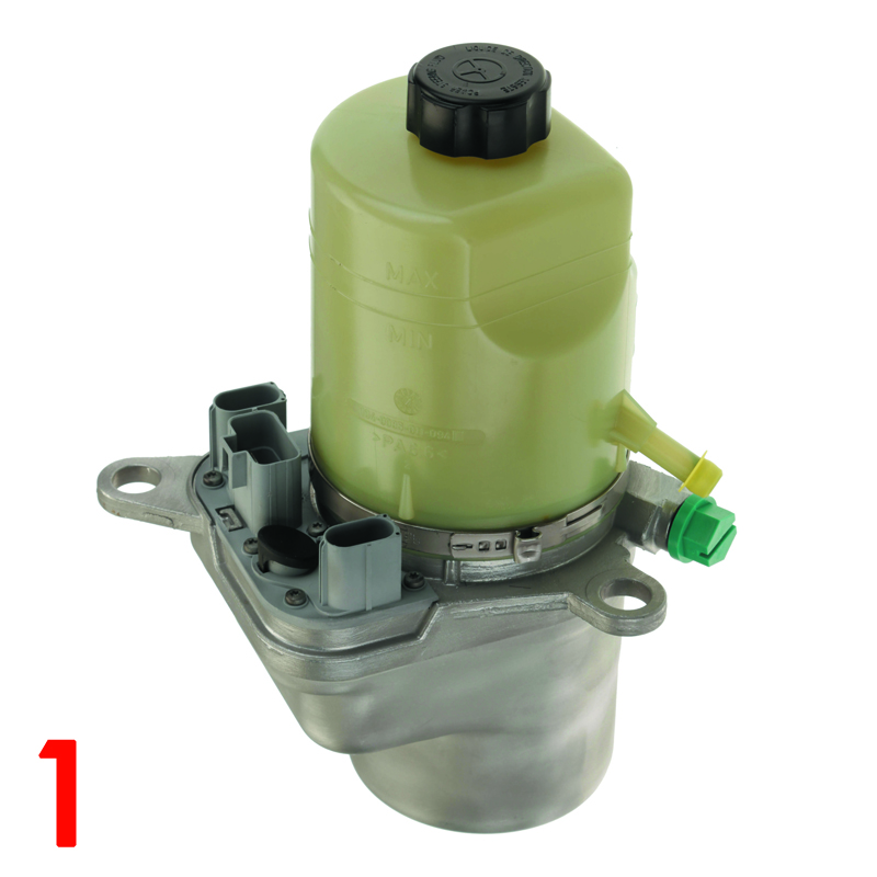
Comprising a compact motor pump unit and conventional rack-and-pinion steering, the system operates independently of the combustion engine, which helps to reduce the vehicle’s fuel consumption. The part number for the replacement pump from the TRW range is JER113 (Fig 1).
Replacement procedure
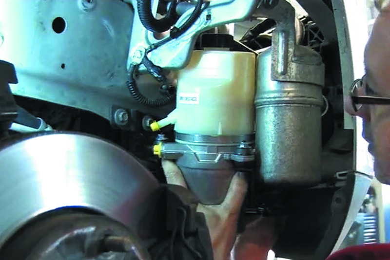
1. Remove the offside front road wheel and the inner plastic wheel arch lining. Remove the front under bumper plastic cover to improve access to the steering pump and its hoses/cables. Before proceeding further, compare the new pump with the one fitted to the car. Depending on the production year of the vehicle, a jumper cable may be required to adapt the connectors on the new pump to those of the vehicle wiring loom on later vehicles. This is supplied with the replacement pump and is also available from Ford dealerships, part number 1 466 590 (barcode 5M5T-14B271-AC).
2. Remove as much hydraulic fluid as possible from the pump reservoir. Unscrew the high pressure outlet pipe union and pull the pipe from the pump, catching any released fluid on a white cloth or paper towel for inspection. If the fluid contains dirt or metal swarf, the system should be completely flushed.
3. Remove the clamp from the return line using suitable pliers and pull the line from the pump reservoir. Unscrew the three mounting bolts, manoeuvre the pump out of its bracket and disconnect the electrical plugs – the pump can now be removed from the vehicle. Inspect the connector on the vehicle harness to ensure there are no signs of corrosion due to water ingress.
4. Remove the offside headlight to gain better access for installation of the new pump.
5. Compare the electrical socket on the new pump with the plug on the vehicle wiring loom (Fig 2).
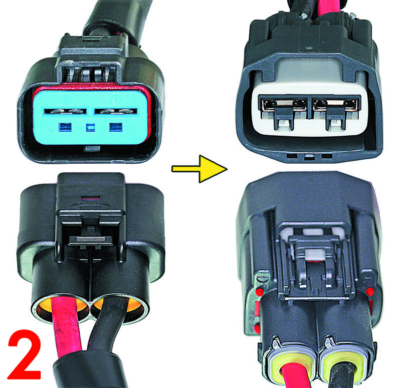
If they match, connect the plug directly to the socket on the pump. Later models have a different connector configuration, and in this instance, the wiring jumper delivered with the pump (Fig 3) must be installed.
Connect the jumper between the socket on the pump and the plug on the vehicle wiring loom, and secure its ground cable to the earthing point adjacent to the pump installation. Remove any corrosion from the earthing point first, and use a new screw to ensure sound electrical contact.
6. Install the new pump in its bracket and secure with the original mounting bolts, torquing them to the vehicle manufacturer’s specification. Reconnect the return hose to the pump reservoir and clamp in place, then connect the high pressure outlet pipe and torque the union nut to its specified value.
7. With the pump in position and all connections made, the system can be refilled and bled. Remove the filler cap from the pump reservoir and fill to the ‘MAX’ level mark with the vehicle manufacturer’s recommended fluid. Raise the vehicle until the front wheels are clear of the ground. Start the engine and immediately recheck the fluid level in the reservoir, as it may drop quickly. With the engine idling, slowly turn the steering wheel 10-15 times from left to right without reaching the steering limit. Keep a check on fluid level at all times, then top up to the ‘MAX’ mark and replace the reservoir cap when bleeding is complete.
8. Re-install the headlight, the inner plastic wheel arch lining, the under bumper plastic cover and any other components that were removed for access. Check and adjust the headlight aim as necessary.
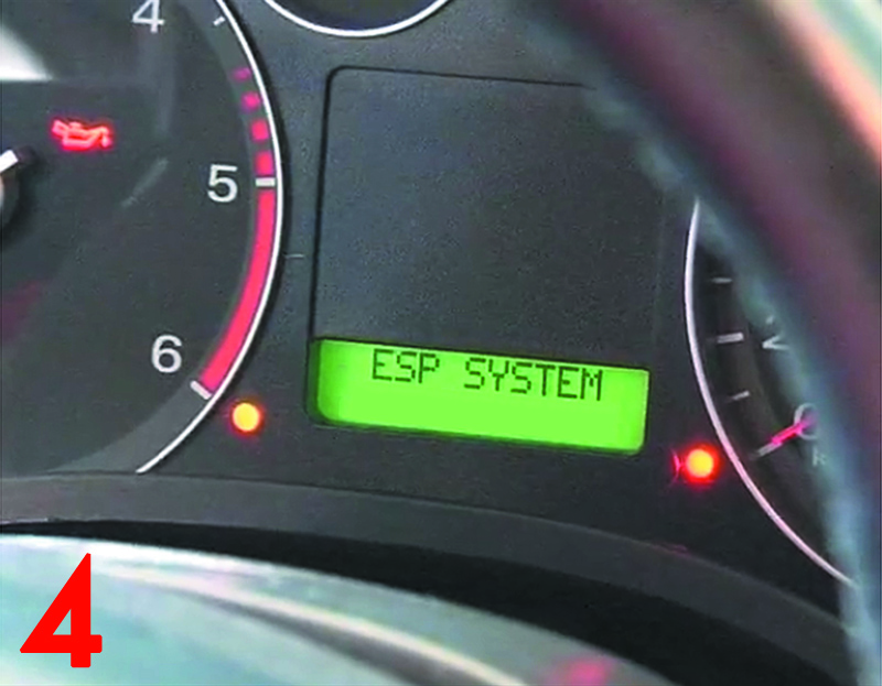
9. Clear any diagnostic fault codes before coding the new pump to the vehicle (Fig 4). In the case of pump JER113 described in these instructions, specific maps need to be loaded into the memory of the steering pump ECU using appropriate diagnostic equipment. From the diagnostic menu, load and activate the map corresponding to the vehicle.
10. Finally, take the vehicle for a test drive.
TRW parts labelling explained
When installing electric steering columns, steering gearboxes, or electrohydraulic power steering pumps, the newly installed parts may require programming or calibration. TRW parts packaging includes labels that indicate this.
A yellow label (Fig 5) indicates components that require coding to the vehicle. It may be necessary to calibrate the steering angle sensor, redefine the steering wheel position, or select a corresponding characteristic map. A QR code printed on the label directs the workshop to the required measures for particular part numbers.

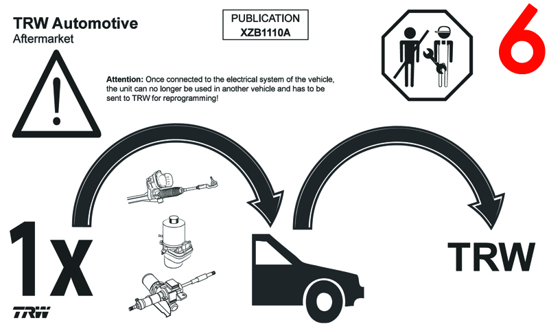
If a white label (Fig 6) is also on the packaging, once the component has been connected to a vehicle’s electrical system it cannot be used in a different vehicle without first being reprogrammed by TRW.
If neither label is on the packaging, the component is a ‘plug and play’ item that needs no further programming after being installed in the vehicle. A short description of the different programming steps that may be required after installation of electrical steering pumps, steering gears and steering columns include:
Calibration steering angle sensor
After installing the column drive/steering pump, the steering angle sensor must be calibrated according to the vehicle manufacturer’s specification.
Load/select map
After installing the column drive/steering pump, specific maps must be loaded into the column drive/steering pump ECU memory using a suitable diagnostic tool. After loading the maps, the map corresponding to the vehicle can be activated in the column drive/steering pump.
Set absolute steering position
After installing the column drive/steering pump, the absolute steering position must be configured using a diagnostic system and by turning the steering wheel from one limit stop to the other.
Map selection
After installing the column drive/steering pump, the corresponding pre-loaded map for the vehicle must be activated using a suitable diagnostic tool.
VIN programming
After installing the column drive/steering pump, the vehicle identification number (VIN) must be entered into the memory of the ECU, either manually or automatically, using a suitable diagnostic tool.