PMM hears from Steve Scott, Founder of The SimplyDiag Network Ltd, on how to make the most of the data available to you when approaching a diagnostics dilemma.
It’s all too common these days to see requests for wiring diagrams on forums and chat groups from technicians that don’t subscribe to a Tier 1 information source. Systems, such as the Hella Gutmann Solutions’ (HGS) data system, are extremely affordable and can streamline the entire diagnostic process. There is now a responsibility for all workshops to supply their technicians with regularly updated and accurate information in order to diagnose faults accurately and supply customers with the best possible service.
2007 Ford Ka 1.3i petrol vehicle – lambda sensor fault
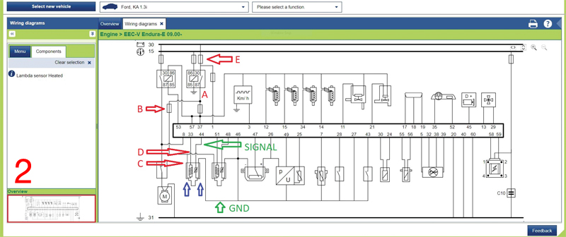
Fig 1 is a screenshot from HGS data. At first glance it may seem complicated, but once technicians understand the basic layout, it very soon starts to make sense. The diagram gives an overview of the engine management system and although it’s basic because of the year of the vehicle, it gives a lot of valuable information regarding the electrical circuit and test points without intrusive testing.
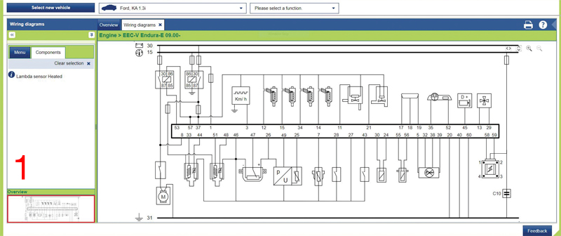
Here’s a list of those test points:
A. Output from the engine management relay to O2 sensor heater circuit
B. Fuse protecting O2 sensor heater circuits
C. Power supply into O2 sensor heater circuit
D. Engine control unit (ECU) controlled Ground (GND) to activate the heater circuit – constant or PWM (Pulse Width Modulation) controlled
E. Fuse protecting Terminal 30 constant supply from battery to engine management relay
Signal: as the name suggests, the evaluation side of the sensor sends its signal to the ECU
GND: The ground completing the circuit for the evaluation/measuring side of the sensor
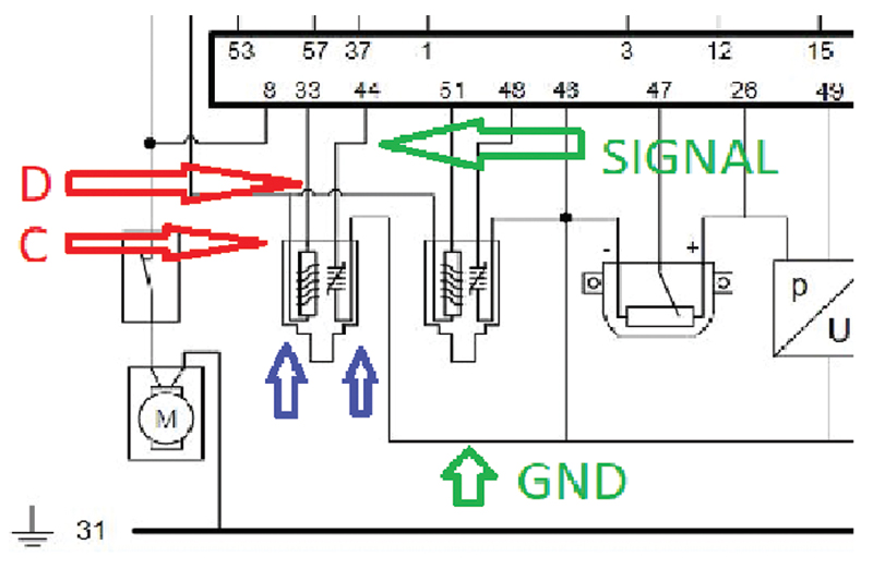
Fig 2 clearly shows that there are two separate but integrated sides to the component; a heater side, which rapidly brings the sensor up to operating temperature and maintains it; and the sensing/evaluation or measurement part, which reads the oxygen content in the exhaust gases, converts that into a voltage and then returns it to the ECU.
If technicians dissect the diagram and focus purely on the sensor itself, they have an opportunity to carry out four quick voltage measurements and one current measurement (if required) to satisfy themselves of the circuit integrity, thus avoiding costly component replacement for a simple blown fuse or poor connection. It also means that they do not run the risk of stripping the sensor threads when removing it unless absolutely necessary.
The critical test points are C, D, Signal and GND, and are all readily accessible on this vehicle without the need for significant dismantling to gain access to the connector.
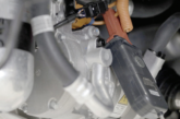
Fig 3 gives a clue as to what technicians may find on the wires, as both the heater and Signal GNDs run through the ECU, and not to the main GND (T31).
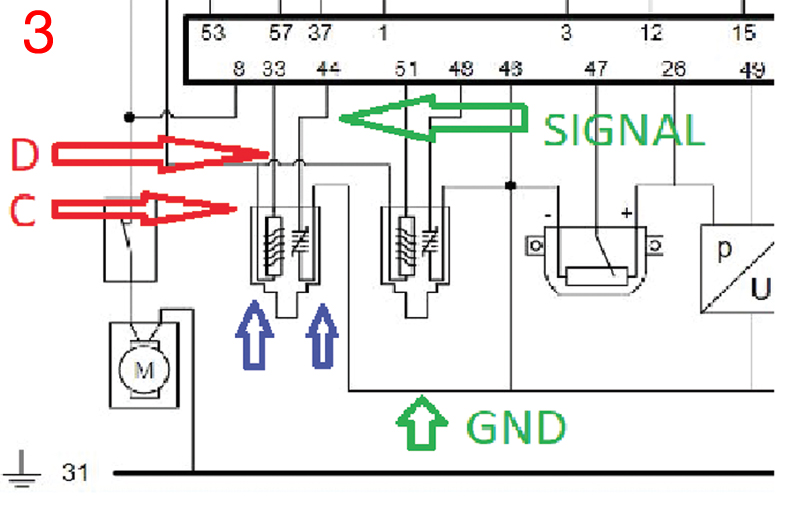
They should find a Pulse Width Modulation (PWM) or Duty Cycle control on D and a GND, with possibly elevated voltage on the signal GND circuit to help shield noise.
Technicians should find the following when testing at the O2 sensor connector with it still secure (either back probing or piercing the wire with a good quality probe):
- C should be a constant supply with the ignition on or engine running
- D should be a PWM (square wave) GND when the sensor heater is activated and when battery voltage is switched off or deactivated. This one measurement on this particular vehicle alone shows that the heating element inside the sensor is electrically intact.
- Key on with a cold engine, technicians would want to see between 450-650mV on the signal wire. Anything higher or lower would indicate further checks are required.
- The signal GND would normally be around 10mV on this vehicle. Again, there are variables, such as in certain circumstances when the GND voltage is raised to allow the ECU to differentiate between sensor output and electrical noise, although not in this case.
These simple tasks: finding a diagram, a volt meter, a test light and carrying out the tests, are the first logical steps in gathering evidence for further testing. Here are the next phases:
- Depending on what is found, zoom out, look at the bigger picture and test at points B, A and E for heater supply
- Pin 33 at ECU to check ECU control of the heater circuit and wiring integrity – a volt drop measurement is ideal
- An inductive current clamp can be used to see the actual current flow in the heater circuit (typically between one and two Amps)
- Volt drop test from Pin 44 to sensor for signal wire integrity
- Volt drop test from Pin 46 to sensor for sensor GND integrity, with the circuit turned on and loaded
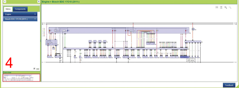
For comparison, Fig 4 is a 2012 Vauxhall Corsa diagram, in colour with components highlighted. On the Hella Mega Macs 77, it’s fully interactive, so technicians can see actual, live values from the sensors and controllers on the diagram.