
Wheel vibration, vehicle pull and drift issues can be a real problem for workshops. They can be the source of considerable customer dissatisfaction resulting in many return trips to the workshop, repeated diagnosis attempts by technicians and, in the worst cases, rejection of replacement parts or tyres. Often a full wheel alignment check and subsequent corrections can resolve these issues. However, in some particularly stubborn cases the problems remain, leaving customers unhappy and workshops confused.
Thankfully though, with the new Hunter Road Force Touch balancer, workshops can take their diagnosis to a new level and resolve even the trickiest issues that standard alignment and balancer combinations may struggle to fix.
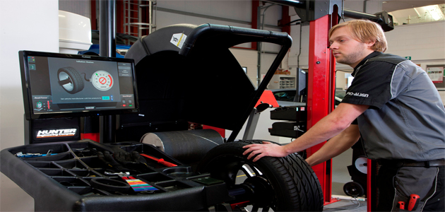
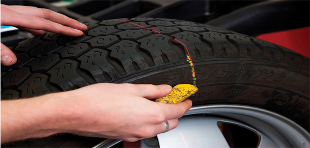
1. REMOVE ALL WEIGHTS AND FIT WHEEL TO BALANCER
The technician removes any wheel weights already on the rim and fits the tyre and wheel assembly onto the balancer. The tyre is then inflated to the correct pressure using the on-board inflation station. The data set arms are used to perform a wheel dimension check which includes the spoke locations so that weight can be hidden later on. The interactive display intuitively guides the technician through the entire balancing procedure with live 3D graphics.
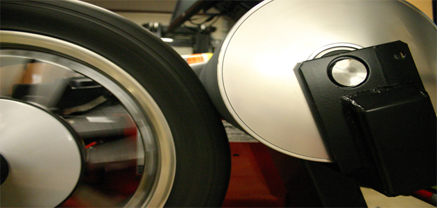
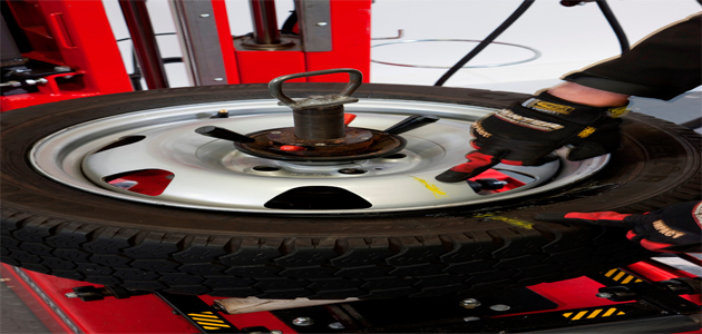
2. HOOD DOWN AND SPIN
Once the hood is lowered, a standard balance check is performed. Then, while still spinning, a load roller is applied, placing up to 560kg onto the tyre, taking it on a simulated road test. This measures the Road Force Variation of the wheel and tyre assembly which is a contributing cause of vibration. In the second stage of the loaded tyre test, lateral force is also measured to determine whether the conicity of the tyre is causing pull.
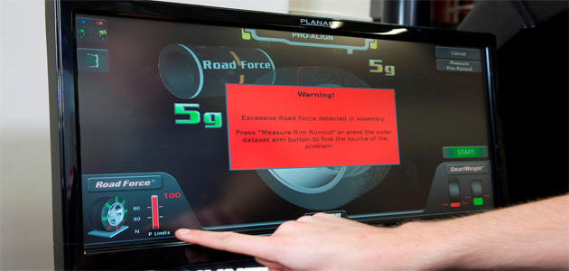
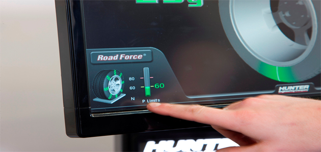
3. THE ROAD FORCE TEST
The hood automatically lifts and the results of the road test are shown. If all measurements are within tolerance, the graphic will be shown in green, highlighting that just the balance weights need to be added. The balancer will show where to locate the weights, taking into account the location of the spokes and the wheel dimensions taken by the technician in step 1. If an excessive Road Force is detected, a red box will appear indicating this and the amount of force will be displayed.
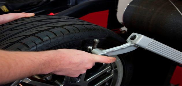
4. RIM RUN-OUT MEASUREMENT
With excessive road force in the assembly, the Road Force Touch will ask the technician to perform a radial rim run-out measurement using the data set arms. This measures whether the rim is out of round and locates the wheel rim ‘low spot’.
5. FORCE MATCHING
At this point the Road Force Touch has formulated the best location for matching the tyre on the wheel rim to minimise vibration. The Servo Stop drive rotates the assembly to indicate to the operator and allow them to place a chalk mark, where the stiff spot of the tyre and the low spot on the rim are.
6. MATCH-MOUNTING
The assembly can then be taken to a tyre changer allowing the two chalk lines to be matched together by rotating the tyre on the rim.
7. RE-SPIN CHECK
A quick balance and simulated road test spin of the modified assembly gives a green graphic verifying the wheel is balanced and within force tolerances to assist smooth rolling with a minimised vibration. Add balance weights as indicated to finish the procedure.
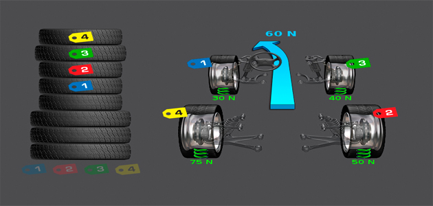
8. LEAST VIBRATION OR PULL PLACEMENT
There’s still one last trick from the Road Force Touch. Hunter delivers the ultimate in customer satisfaction by suggesting the optimal wheel placement with its StraightTrak feature. With each wheel measured, the Road Force Touch will ‘tag’ each wheel in measurement order 1,2,3,4 (the technician does this on the wheels themselves). Recalling the data from the measurement stage, the technician can request a vehicle plan for either ‘Least Vibration’ or ‘Least Pull’.


