In its first contribution to PMM, the IVS 360 team explains how it went about supporting a workshop with a 2013 Range Rover showing a critical suspension fault warning.
Vehicle information
Brand: Land Rover
Model: Range Rover L405
Year: 2013
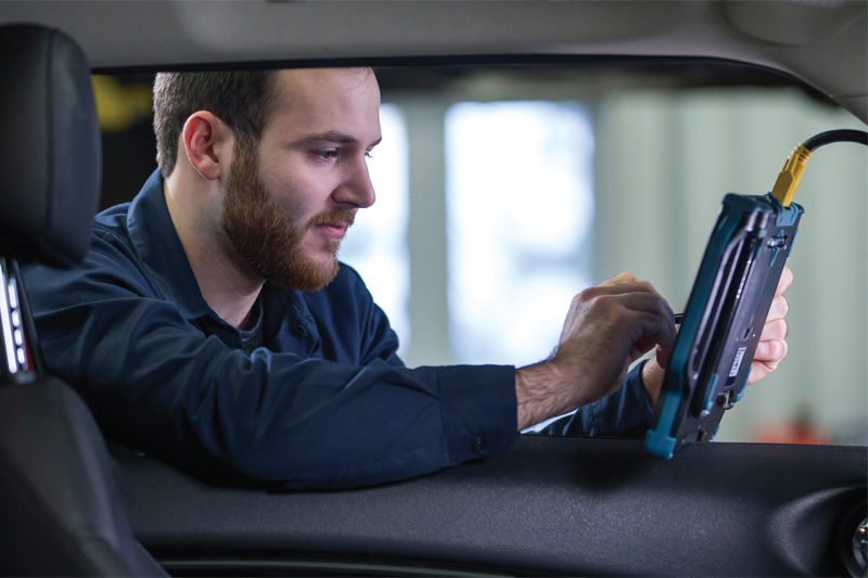
Opus IVS OEM-trained Master Technicians support customers in the automotive aftermarket via its IVS 360 diagnostic support service delivered from its head office in Oxford. Using the DrivePro’s diagnostic software and extensive product knowledge, the IVS 360 team identifies the cause and steps needed to fix vehicle faults. The experts remotely dial-in directly and in real time to vehicle communication systems to diagnose, program and calibrate vehicles.
A recent IVS 360 case during lockdown involved a Range Rover 2013 model, with a suspension fault. Using his extensive Land Rover expertise, IVS 360 Master Technician Terry Oakfield supported the customer with the following advice:
Symptoms
A ‘suspension’ fault displayed on the instrument panel cluster with a ‘critical warning message (red)’. A red triangle with an exclamation mark in red was showing, signifying a critical warning and therefore needed to be looked at immediately. Details of the warning can be seen in the message centre.
Fault codes
- C1041-22 Front Axle Piston Pressure Sensor [Signal Amplitude > Maximum]
- C1043-22 Rear Axle Piston Pressure Sensor [Signal Amplitude > Maximum]
Using Opus IVS diagnostic software and his extensive product knowledge for Jaguar/Land Rover, Terry provided the necessary steps to find the fault using the fault codes and the initial information provided.
Recommendation
Terry suggested some initial ‘first checks’ to begin the process of identifying the fault. These checks are based on the fault codes stored in the Dynamic Respose Module, and are as follows:
C1041-22 Front Axle Piston Pressure Sensor – Signal amplitude > maximum.
- Dynamic response front actuator pistonside pressure regulating valve coil negative circuit – short circuit to ground/open circuit
- Sensor fault
- Dynamic response front actuator piston-side pressure regulating valve – internal failure
First, check the dynamic response front actuator piston-side pressure regulating valve coil negative circuit for short circuit to ground/open circuit. After inspection and should it be required, repair the circuit, clear the DTC and then retest. If the fault persists, then check and install a new dynamic response valve block as required and reset the adaptive data. Once again, clear the DTC and retest.
C1043-22 Rear Axle Piston Pressure Sensor – Signal amplitude > maximum
- Dynamic response rear actuator piston-side pressure regulating valve coil negative circuit – short circuit to ground/open circuit
- Sensor fault
- Dynamic response rear actuator piston-side pressure regulating valve – internal failure
To address this fault code, refer to the electrical circuit diagrams and check the dynamic response rear actuator piston-side pressure regulating valve coil negative circuit for short circuit to ground/open circuit. Again, repair the circuit if it is required, following this up by clearing the DTC and carrying out a retest.
If this fault persists, check, and install a new dynamic response valve block as required and reset the adaptive data. Finally, clear the DTC and retest.
Next steps
Terry continued the diagnostics process by explaining to the customer that there was a response valve block located on the underside of the LH centre inner sill. He went on to ask the technician to check the wiring on the valve body but specifically for the front axle piston-side pressure regulating valve coil.
Terry provided the following information for the circuit that needed checking:
Connection detail
C3CL54E: Module-Control-Dynamic response Location Right A-pillar Brown with23 cavities
C31-M1: Main harness to valve block harness Black with eight cavities
C1CL41H: Valve Block-Dynamic response Location Beneath vehicle – Left Hand Front under the plastic tray between inner sill and floor pan Black with four cavities
C3CL54E-02 White-Brown to C31-M1-08 to
C1CL41H-04 Power supply
C3CL54E-03 White-Green to C31-M1-02 to
C1CL41H-01 Ground supply
Check for a short circuit to ground, short circuit to power, short circuit to another circuit, open circuit, resistance, and with connectors undone at each end load test the wiring with a suitable bulb (21W or 55W H7).
With this completed, Terry asked the technician to check the wiring on the valve body but specifically for the rear actuator piston-side pressure regulating valve coil, providing the following information for the circuit that needed checking:
Connection detail
C3CL54E: Module-Control-Dynamic response Location Right A-pillar Brown with 23 cavities
C31-M1: Main harness to valve block harness Black with eight cavities
C1CL41G: Valve Block-Dynamic response: Valve Block-Dynamic response Location Beneath vehicle – Left Hand Front under the plastic tray between inner sill and floor pan Black with four cavities
C3CL54D-05 Black-Violet to C31-M1-10 to
C1CL41G-04 Power supply
C3CL54D-04 Black-Grey to C31-M1-04 to
C1CL41G-01 Ground supply
Check for a short circuit to ground, short circuit to power, short circuit to another circuit, open circuit, resistance and with connectors undone at each end load test the wiring with a suitable bulb (21W or 55W H7).
Terry explained that as the code states negative circuit short to ground/open circuit, the code is pointing towards the Black-Grey and the White-Green wires being shorted to the vehicle ground or open circuit.
Repair
The customer reported back that the fault lay within the connector C31-M1, pins 02 and 04. These pins were loose in the connector body and backed out, creating an open circuit. To remedy this, pins were fitted correctly in the connector and checked for integrity. The fault codes were cleared and the vehicle road tested.


