TRW Aftermarket provide a 10-step procedure for replacing the EPHS pump on a 2004-2012 Ford Focus II.
Electrically-powered hydraulic steering (EPHS) from TRW combines the advantages of electronically controlled, demand-based steering with robust hydraulic actuation. Comprising a compact motor pump unit and conventional rack-and-pinion steering, the system operates independently of the combustion engine, which helps to reduce the vehicle’s fuel consumption.
Below, Brian Newell, Technical Field Sales Manager at ZF Aftermarket, describes a straightforward 10-step procedure for replacing the EPHS pump on a 2004-2012 Ford Focus II. The part number for the replacement pump from the TRW range is JER113.
Step-by-step guide
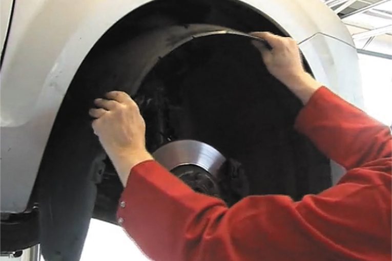
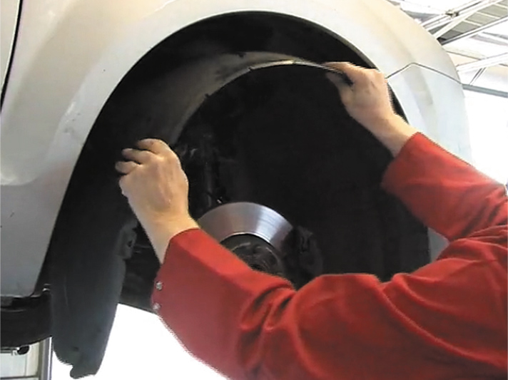
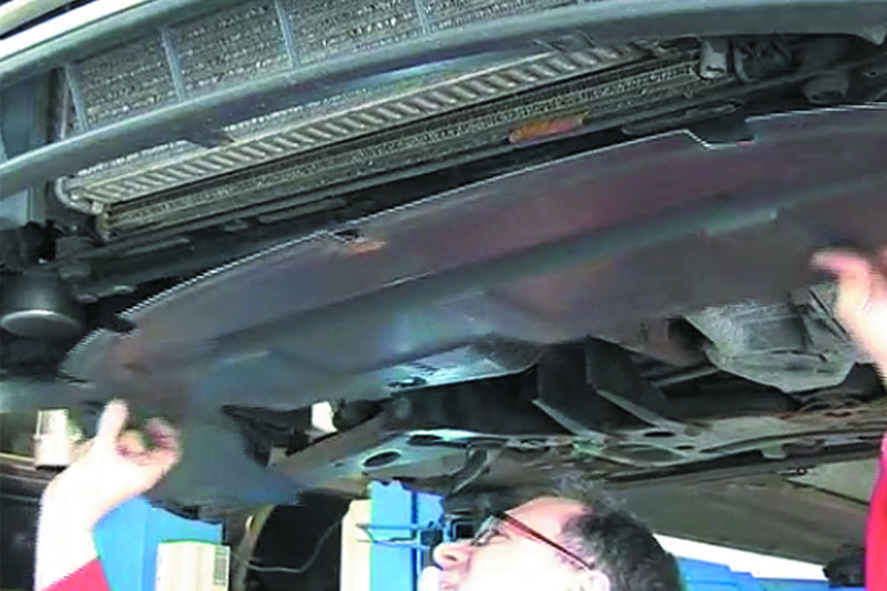
Remove the offside front road wheel and the inner plastic wheel arch lining (see below).
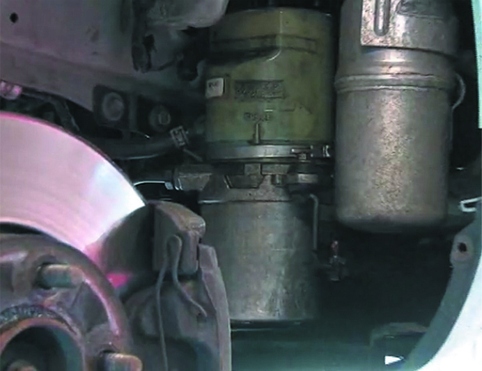
Remove the front under bumper plastic cover to improve access to the steering pump and its hoses/cables. Before proceeding, compare the new pump with the one fitted to the car (see below), checking that all connections and mountings are identical.
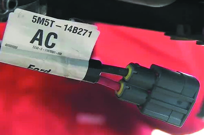
Depending on the production year of the vehicle, a jumper cable may be required to adapt the connectors on the new pump to those of the vehicle wiring loom on later vehicles. This is supplied with the replacement pump – part number 1 466 590 (barcode 5M5T-14B271-AC).
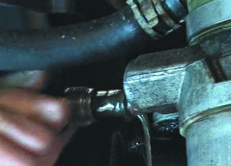
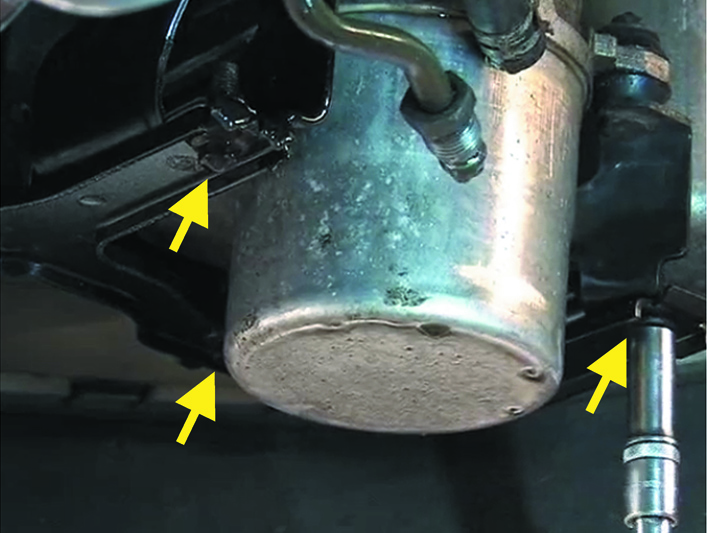
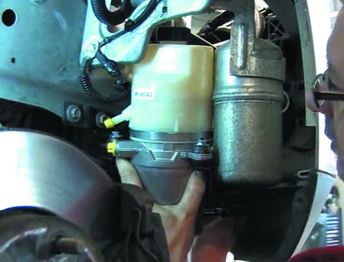
Remove as much hydraulic fluid as possible from the pump reservoir. Unscrew the high pressure outlet pipe union and pull the pipe from the pump (see below), catching any released fluid on a white cloth or paper towel for inspection. If the fluid contains dirt or metal swarf, the system should be completely flushed.
Remove the clamp from the return line using suitable pliers and pull the line from the pump reservoir. Unscrew the three mounting bolts (see below), manoeuvre the pump out of its bracket and disconnect the electrical plugs.
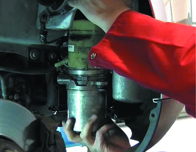
The pump can now be removed from the vehicle (see below). Inspect the connector on the vehicle harness to ensure there are no signs of corrosion due to water ingress.
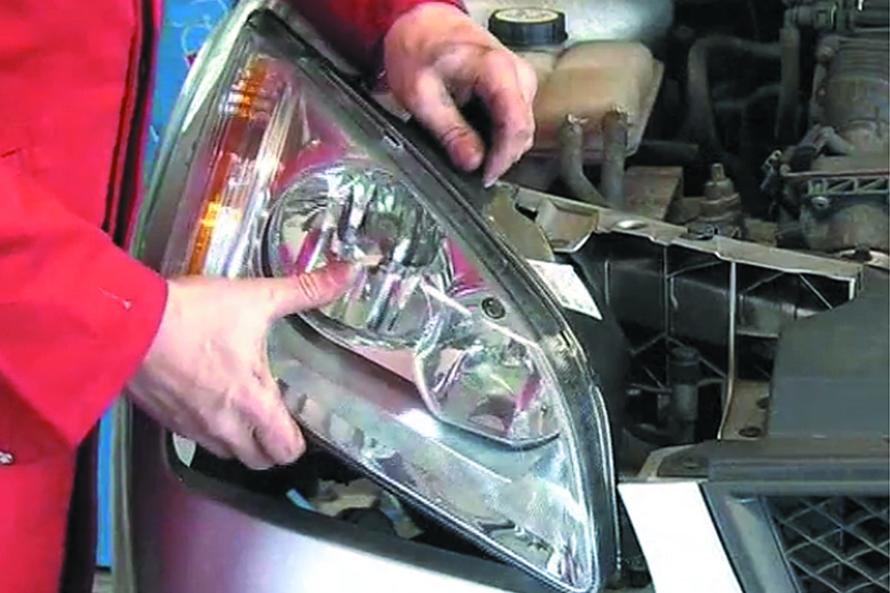
Remove the offside headlight to gain better access for installation of the new pump (see below).
Compare the electrical socket on the new pump with the plug on the vehicle wiring loom (see below).
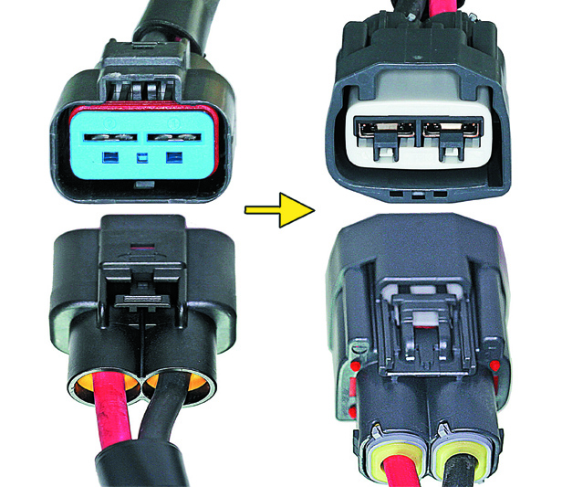
If they match, connect the plug directly to the socket on the pump. Later models have a different connector configuration and, in this instance, the wiring jumper (see below) delivered with the pump must be installed.
Connect the jumper between the socket on the pump and the plug on the vehicle wiring loom, and secure its ground cable to the earthing point adjacent to the pump installation. Remove any corrosion from the earthing point first, and use a new screw to ensure sound electrical contact.
Install the new pump in its bracket (see below) and secure with the original mounting bolts, torquing them to the vehicle manufacturer’s specification.
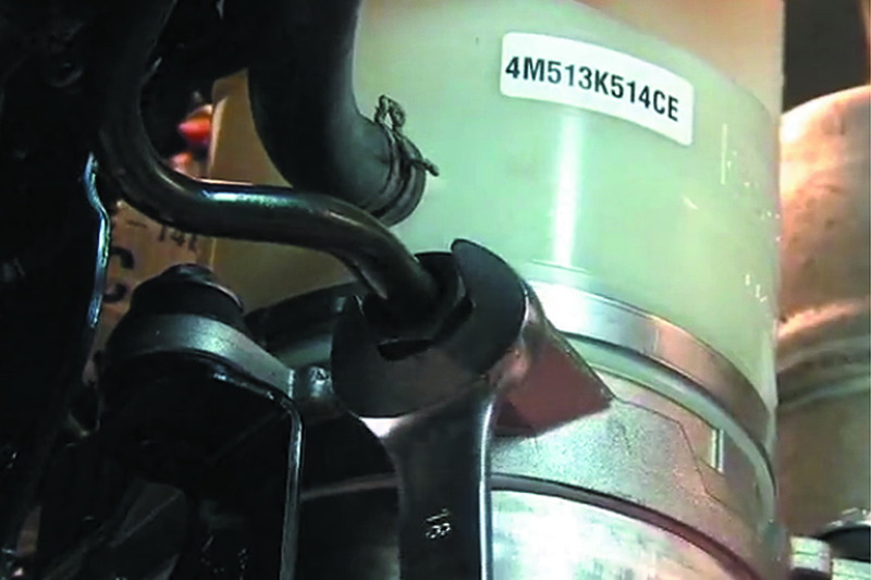
Reconnect the return hose to the pump reservoir and clamp in place, and then connect the high pressure outlet pipe and torque the union nut to its specified value (see below).
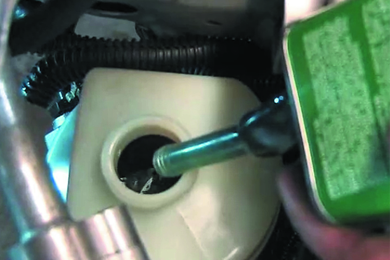
With the pump in position and all connections made, the system can be refilled and bled. Remove the filler cap from the pump reservoir and fill to the ‘MAX’ level mark with the vehicle manufacturer’s recommended fluid (see below).
Raise the vehicle until the front wheels are clear of the ground. Start the engine and immediately re-check the fluid level in the reservoir, as it may drop quickly. With the engine idling, slowly turn the steering wheel 10-15 times from left to right without reaching the steering limit. Keep a check on the fluid level at all times, then top up to the ‘MAX’ mark and replace the reservoir cap when bleeding is complete.
Re-install the headlight, the inner plastic wheel arch lining, the under bumper plastic cover (see below) and any other items removed for access. Check and adjust the headlight aim as necessary.
Clear any diagnostic fault codes before coding the new pump to the vehicle (see below).
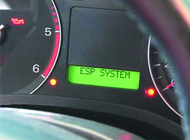
In the case of pump JER113, specific maps need to be loaded into the memory of the steering pump ECU using appropriate diagnostic equipment. From the diagnostic menu, load and activate the map corresponding to the vehicle.
Finally, take the vehicle for a test drive.
Provided the old pump is in satisfactory condition, the core surcharge included in the cost of the replacement unit can be reclaimed. Check that there is no damage to the pump housing, the mounting points, the pipe union threads or cable sockets, and that the reservoir is intact, with its lid present and undamaged. Seal the connections for the hydraulic lines and the sockets using the plugs and connector caps supplied with the new pump, then attach the red label to the pump and return it to your supplier for credit.


