
Case contents (p/n 60385395/60385400): base plate, collar nut (M14), support leg (adjustable), lubricant, swivel cup collar , knurled nut (M18 x 1.5), leg extension, RAM (12t), swivel cup, tensile spindle (M18 x 1.5, 5 x 242), allen wrench.
Recommended assembly and operational tools (not included with set): combination wrench (19) or socket (19) with ratchet; combination wrench (17) or socket (17) with ratchet; ¼”ratchet with socket (10); hydraulic pump with hose and ball valve.
This guide and the recommended tools shown are meant to serve as aides only and are by no means a guarantee for a removal. In some cases, due to insufficient space the engine or the cylinder head will need to be removed. The tool kit used in this example is a special collection and has been tested and used successfully on several occasions. It is of the utmost importance to follow the correct OEM manufacturer sequence.
1. Selecting support points
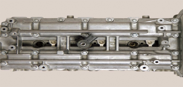
Only solid, well supported and fixed points (preferably screw heads) on the cylinder head are to be used. When connecting the support points in a straight line the injector must be located inside the resulting triangle.
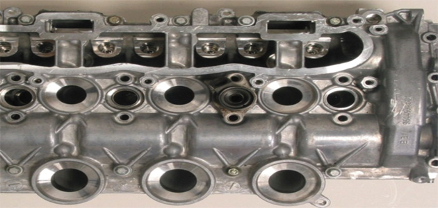
2. Sizing the support surface
Depending on the form of the points of support on the cylinder head (i.e. screw heads or well supported, solid flat surfaces) the proper support surface for the extractor needs to be chosen.
There are two versions to choose from:
a) Support leg without extension to the spindle (for small support surfaces) – the supporting spindle must not protrude from the horizontal arm.
b) Support leg with extension to the spindle (for large support surfaces) – the extension for the support leg must be screwed until the stopping point on the spindle and properly tightened.
3. Positioning the base plate
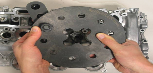
When placing the support leg on the first point of support, check that there is sufficient room to extract. If necessary, screw out the spindles. Feed the slot bolt through a random hole on the base plate and screw the collar nut on the bolt before hand-tightening it. Position the centre of the base plate centrally above the injector.
Position the second and third support leg on the support points 2 and 3. The positions of all three slot bolts in the base plate must be chosen so that the base plate is supported by the support legs and the base plate is centred above the injector. Tighten the collar nuts M14 with a suitable tool to approx 80-100Nm.
4. Aligning the base plate height
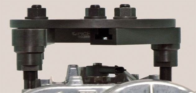
By screwing in and/or out of the spindles, align the base plate parallel to the cylinder head. The base plate doesn’t necessarily need be parallel to the injector, but always has to be in line with the support points.
5. Disassembling the injector
Remove the base structure and dismantle the injector as far as necessary to be able to mount a suitable adapter. Our recommendation is to use the designated injector removal and adapter set (p/n 60384660) from Pichler Tools.
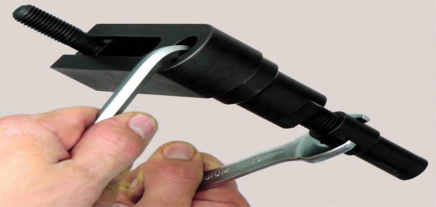
6. Screwing in the tensile adapter and spindle
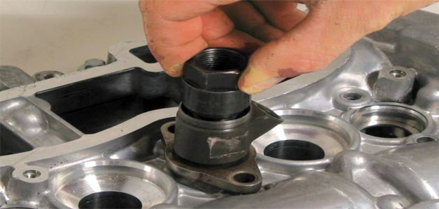
Screw in and tighten the appropriate tensile adapter on or into the injector. Screw the tensile spindle into the tensile adapter and tighten it with a ratchet and socket.
7. Placing the base structure and removing the injector
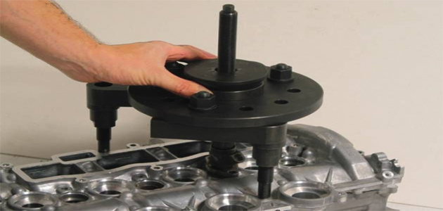
Place the base structure over the tensile spindle onto the cylinder head. Place swivel cup collar and swivel cup over the tensile spindle, onto the base plate. Make sure that the arrow on the swivel cup collar points in the direction of the base plate and cylinder head.
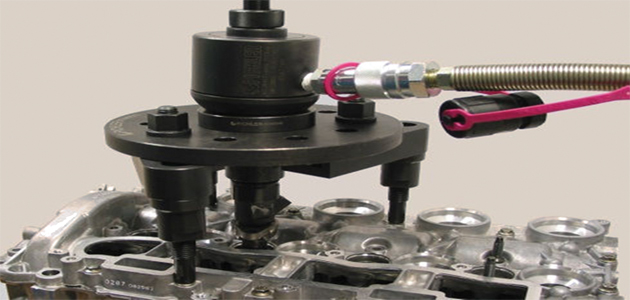
Place the RAM over the tension spindle on the swivel cup. Screw the knurled nut on the spindle, connect the RAM to a hydraulic hand pump (max operating pressure 700 bar) and start pumping.
After about 8mm the maximum stroke of the piston is reached. Release the pressure, tighten the knurled nut by hand and start pumping again. Repeat the process until the injector is released.


