

Following on from last month’s article about the importance of a clear diagnostic process, technician Ben Martins finishes the job.
Last month, we ended with a list of possible causes of the issues that the customer’s car was experiencing. This leads us to the next step in the process:
Create an action plan based on accessibility and probability
Although this might seem like a waste of time, this can really keep things focused when time is against you. From the list in the previous issue, there are some easy ones which can be checked straight away: power and ground.
If there is an ECU with no power supply, it is effectively offline and therefore won’t be seen by the other ECUs. Nobody likes making the call on an ECU, so let’s cover all other options first. You could stick with the manufacturer’s diagnostic route at this point, but the problem with doing so is that if you were to follow it through, you would put a TAU on the vehicle and the fault would still be there. Personally, I would much rather be a little more open-minded and come up with my own action plan.
With the TAU by the driver’s side kick panel, it is easy to get to. Power and grounds need to be checked, and as there was a “communication” DTC, I wanted to see the network signal.
Apply PicoScope in the most non-intrusive way possible
This can be tricky, but sometimes you have to do what is necessary. With this particular case, I had to adopt back-pinning, which is regarded as intrusive testing. As the plug didn’t have any waterproofing seals, there was no need to pierce the insulation. Therefore, the back- pinning probes could be inserted carefully between the plug casing and the terminal.
Apply PicoScope intrusively if required based on repair process
Starting with supply, I wanted to see if the ECU was receiving power and had an earth. A meter would have been adequate, but as I already had my PicoScope out, I had a way of recording all of my information and observing both tests at the same time. With the correct wiring diagram and the ignition turned on, I had battery voltage at the supply wire and 0V at the earth.
Next on the list is wiring. As the CMU communicates with the TAU via a CAN network, this seemed to be a likely cause from the action plan. Reading the description further, its detection condition was ‘the connectivity master unit (CMU) cannot receive a CAN signal from the tuner and amp unit (TAU) for five seconds or more.’
Does this mean that the ECU wasn’t responding, it was offline, or there was an issue with the CAN wiring? We know this is a small CAN network with two terminating resistors which are likely to be 120Ω. In order to measure this correctly, the power supply needed to be removed, so with the customer’s settings saved, the battery negative was removed. Consulting a wiring diagram, I was looking for the easiest way onto this network, and discovered a little check connecter which sat just above the OBD port. I’m not entirely sure of the purpose of this connector, but it meant I could be certain that there were only two wires at this plug; CAN H and CAN L.
A quick resistance measurement saw the 60Ω expected from CAN, providing this network had two 120Ω terminating resistors on this network.
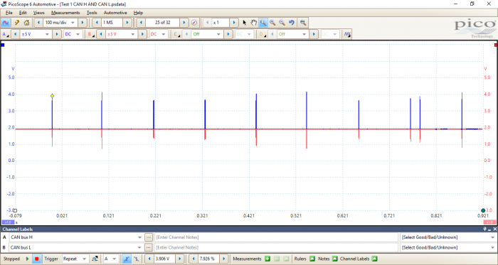
With the wiring in front of me, the next step was to look at the data for integrity. Attaching Channel A of PicoScope to CAN H and Channel B to CAN L, I could see both sides and ensure that data was being transferred. Even with serial decoding, I couldn’t verify which ECUs were sending or requesting data, but I could see if it was there for a start. I was only looking for signs of communication to begin with, so a longer time base was used.
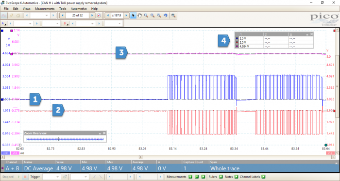
At first glance at Fig 1, it seems clear that data was present and that it was being seen in both CAN H and CAN L, but once you look closer, there appears to be something irregular with the signal.
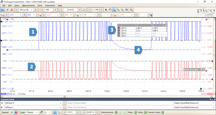
What stands out in Fig 2 is CAN Low. As you can see, at point 2 the idle voltage starts in the middle of the data packet rather than being pulled down from the 2.5V typically seen in most CAN networks. However, what’s also interesting is that when the network is broadcasting data, the network adjusts to where we see CAN H between 2.5 and 3.5V, and CAN L at 1.5 and 2.5V.
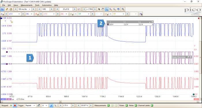
Using the Tools menu and selecting ‘Maths’, I used the A-B preset to allow me to look at what the ECUs would be seeing once they had seen the data packets. Now, this is why CAN is regarded as fault tolerant. Despite the fact that there was an issue with the idle voltage of the network, when we perform A-B, it still switched between the 0 and 2V that was expected. As both sides of the network were affected by the same issue, when one is taken away from the other, they cancel each other out. When dealing with CAN faults, I try to use both A-B and A+B.
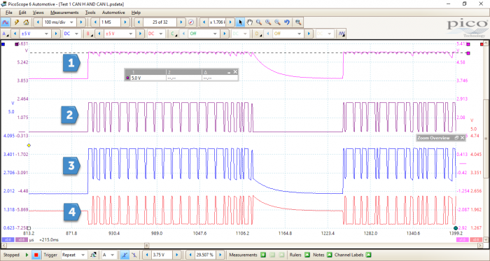
If we add points 3 and 4 from Fig 4 together, the result should remain around 5V, whether the network is idle or transmitting. I had already suspected a voltage issue, but by using some simple maths, I was able to quickly see the area of interest.
Now would be a good time to recap
1) There were no faults stored in the CMU (Connectivity Master Unit) via serial diagnostics.
2) The audio system had an additional local network where data messages were passed via CAN to the TAU (Tuner and Amp Unit) which sent the audio signals to the speakers.
3) Fault codes for TAU were generated in a separate hidden diagnostic menu, which was accessed by the centre screen. The fault U0184:00 was found for missing messages from TAU stored in the CMU.
4) Power and Ground to the TAU were correct.
5) The local network contained terminating resistors in TAU and CMU. When the network resistance was checked, 60Ω was found. I can’t confirm if this is correct, but I would assume that this network was a high speed CAN network similar to that of the main network present on the car. In this case, there were two 120Ω resistors at each end of the network, giving the 60Ω if the network was intact. I see no reason to believe this was not the case with the local network I had tested, although I have no evidence that 120Ω resistors were used. However, I was able to confirm that the CAN wires – from the CMU to the TAU – weren’t shorted to positive, ground or each other. One method of proving this would have been to carry out a resistance check with the TAU disconnected. If the result was 120Ω, then I would have known that I was correct.
6) PicoScope revealed that the idle voltage for the CAN network was incorrect. It should have been 2.5V, but was instead 1.9V. Despite this, data that could not be decoded was still present.
Continuing with the diagnosis, I believed that an ECU was corrupting the CAN network. The advantageous thing about this fault was that it was on a very small network and therefore didn’t need too much dismantling. My next step was to see what happened if I removed the power supply.
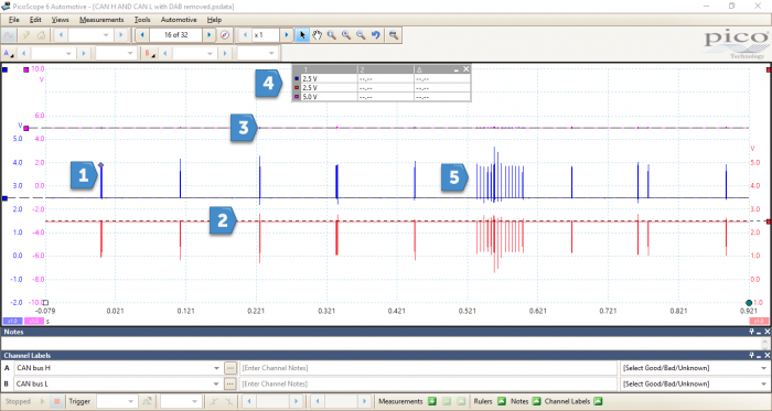
By simply removing the plugs to the TAU, the network rectified itself.
Displayed in Fig 5 is the expected signal for the two CAN lines. When at idle, the network voltage sat nicely at 2.5V and when data was transmitting, the voltages were pulled high or low. I’ve also included the A+B maths channel, which sat around the 5V mark, even when messages were being transmitted. This proved that the fault lay within the TAU, but did this mean that I was ready to throw an ECU at it?
This was a tough call, and one which I certainly didn’t like to make without being 100% certain. In this instance, I had the luxury of having two identical vehicles, one of which had no fault with its audio system. Double checking that the specifications were all the same, I decided to fit this TAU to the faulty vehicle, with the hope that all was fixed. No such luck.
With both TAUs out, I felt that the ultimate test was to fit the suspected faulty TAU to the non-faulty vehicle and, what do you know, it worked! I know that having the option of a donor car is a luxury, but there are certainly ways around this.
With the knowledge that the TAU wasn’t at fault, I turned my attention back to the drawing board. Looking back at the inputs and outputs of the TAU and keeping it simple, there were two other inputs to the TAU – the AM/FM aerial and the DAB amplifier. By reading the technical information on these two devices, I established that they both carry a power supply. Perhaps it was possible that one of these devices was responsible for affecting the voltage level of the CAN network.
The next step can be applied to those who haven’t got a donor car. Prior to condemning an ECU, I removed any other connectors and kept the power supply and communication wired to the ECU. ECUs all rely on inputs and outputs, and removing them can help to identify whether either could be causing a fault. In this case, removing both of the aerials saw the network voltage re-established to 2.5V, but there was still no functionality from the controls. A cycle of the ignition saw all volume controls restored, and static from the speakers.
Determining which one was at fault was fairly straightforward; I plugged each one in to see what happened. I found that when reconnecting the DAB amplifier antenna, the system shut down and the network voltage went back down to 1.9V. In order to test the DAB aerial, it was imperative that the amplifier connector in the tailgate was showing 8V. By disconnecting and back probing the connector, I saw that 8V was present, which proved that the ECU was sending the correct signal out, and therefore condemning the amplifier. Fitting a new amplifier fixed the fault, and to confirm, I checked to see if the DAB radio worked.
Confirm the repair with PicoScope
This is often an overlooked part of the repair, but it is important to ensure you have the evidence to prove that the fault is fixed. Fig 6 displays a capture of the CAN network with the new DAB amplifier fitted.
From this capture, the A+B maths channel remained consistent at 5V, and the network idle voltage was at 2.5V. Volume and sound settings were able to be adjusted, and all fault codes were erased from the CMU memory.
This isn’t going to be a common fault, but it goes to show that a good diagnostic process can lead to success.


