Pico Technology recently received a case study from Daniel Black, a US Mercedes Benz technician, which showed the process of diagnosing a Mercedes Benz Sprinter 906 suffering from a lack of power.
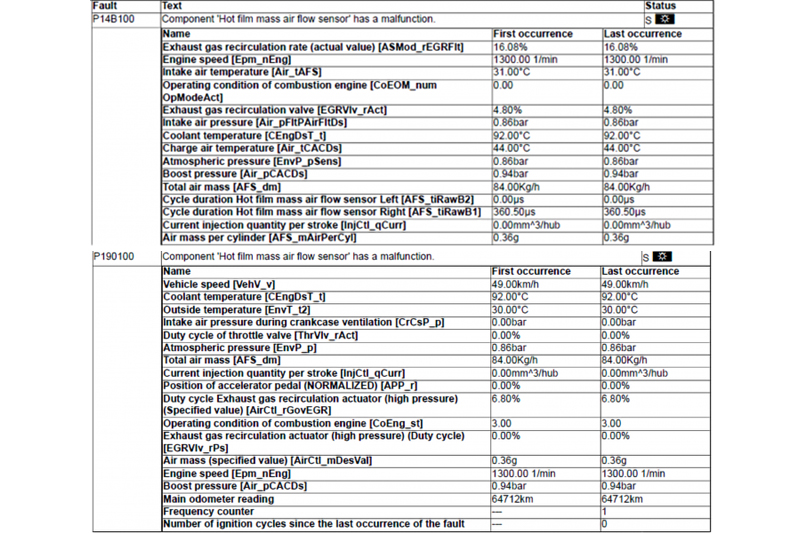
The vehicle came in with the customer complaining that there was a lack of power; the CEL was illuminated and in the customer’s own words, “it feels like it has no boost”. Using the Xentry diagnostic tool, we found two fault codes stored. P14B100 and P190100 were stored in the CDI (commonrail diesel injection). We were not able to obtain any specific information on the criteria for setting these fault codes.
We reviewed the freeze frame data and it was not particularly helpful at identifying the conditions that the fault was set under (Fig 1). The guided tests were run for both stored codes, with the guided test recommending replacement of the mass air flow sensor or inspection of the harness.
Possible causes and remedy
- Check electrical lines and connectors between control unit ‘N3/35 (CDI control unit)’ and component ‘B2/14 (Hot film mass air flow sensor)’ for short circuit, open circuit, loose seating, loose contact and damage using the appropriate wiring diagram.
- Replace component ‘B2/14 (Hot film mass air flow sensor)’.
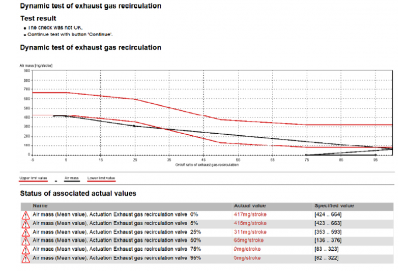
We decided to check the intake system for air leaks. During this test, two leaks after the mass air flow sensor were revealed. These were rectified with no change in operation. Next, we decided that a dynamic EGR test might reveal some helpful information. During this test, we found that the vehicle would occasionally stall and fail the test in all of the specified ranges (Fig 2).
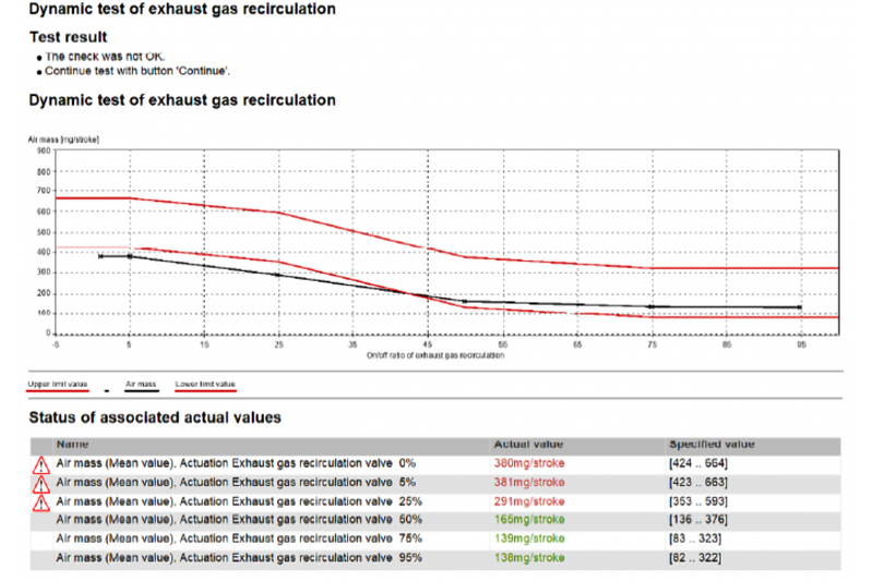
At this point, a known good EGR valve was installed for testing and the test was run again with no change in results. With no improvement, we searched for any technical topics related to these fault codes, finding a few cases relating to pins at the CDI for the EGR recirculation positioner (Y27/17) and the EGR recirculation cooling solenoid (Y27/13). The CDI was disconnected and pin tension was checked; all pins were secure and the CDI was reconnected. After this, the vehicle ran better and passed the dynamic EGR test in the upper ranges, and the engine would no longer stall (Fig 3).
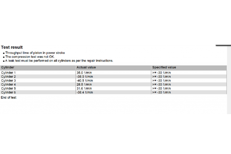
A test drive revealed that most of the power had returned, but the vehicle was still not at full power and the fault codes eventually returned. At this point, the electronic compression test was run and the results were very telling (Fig 4).
With all but one cylinder failing, we proceeded to perform a manual compression test. Bank 1 (cylinders 1-3) were around 18 bar (261psi); bank 2 (cylinders 4-5) were below 12 bar (174psi) – the wear limit for this engine is 17 bar (246psi). A leak down test was performed on bank 2 with 8% leakage on cylinder 4, and 4% on cylinders 5 and 6. The extra leakage on cylinder 4 was found to be coming past the injector seal, but it was not enough to cause this loss of compression on bank 2. With good leak down readings, we were initially at a loss for what would cause a loss of compression.
Hypothesis
After thinking it over, I decided that a restriction on the intake side of bank 2 might explain the loss of compression and would still give us good leak down numbers. I decided to take in cylinder compression readings with the Pico Scope to get a better idea of what was going on.
Materials
- Pico Scope 4425
- WPS500x Pressure Transducer Kit
- Glow plug adaptor
Procedure
- Attached WPS500x to cylinder 1 glow plug range 1
- Battery maintainer attached to vehicle
- Fuel system disabled
- Pico set to 200ms/div, sample rate 1ms, scale 500psi
- Cranked engine until speed was stable
Results
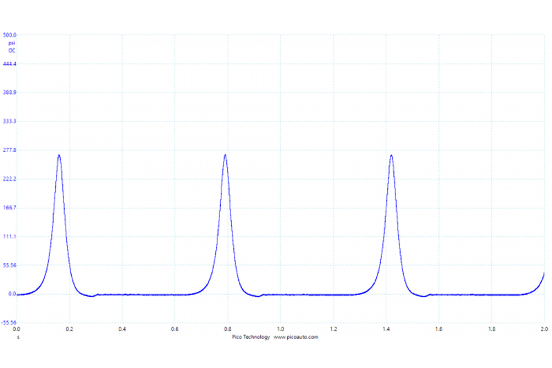
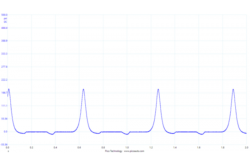
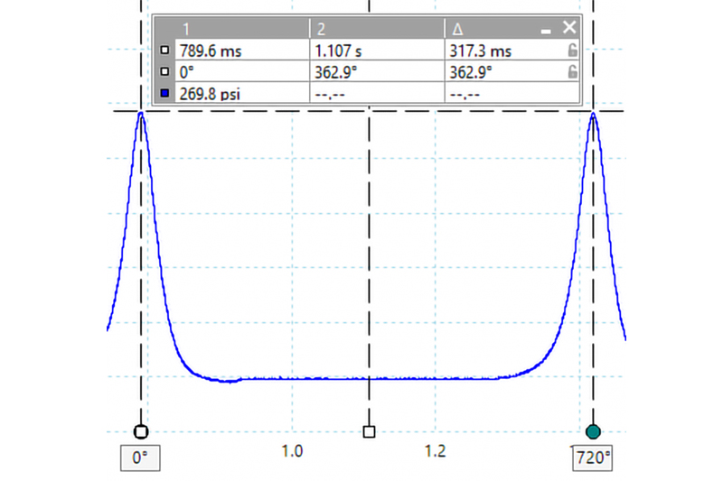
Right away we can see a clear difference in peak compression and a distinctive pocket near the intake stroke on cylinder 4 (Fig 6); cylinders 5 and 6 were nearly identical. Using the measuring tools and comparing it to the known good cylinder (Fig 5), I revealed some very interesting information. Looking closely at the good cylinder, we can see a peak cylinder pressure of 269.8psi (18.6 bar). We can also see that the intake valve is opening approximately 362.9 degrees after compression TDC (Fig 7).
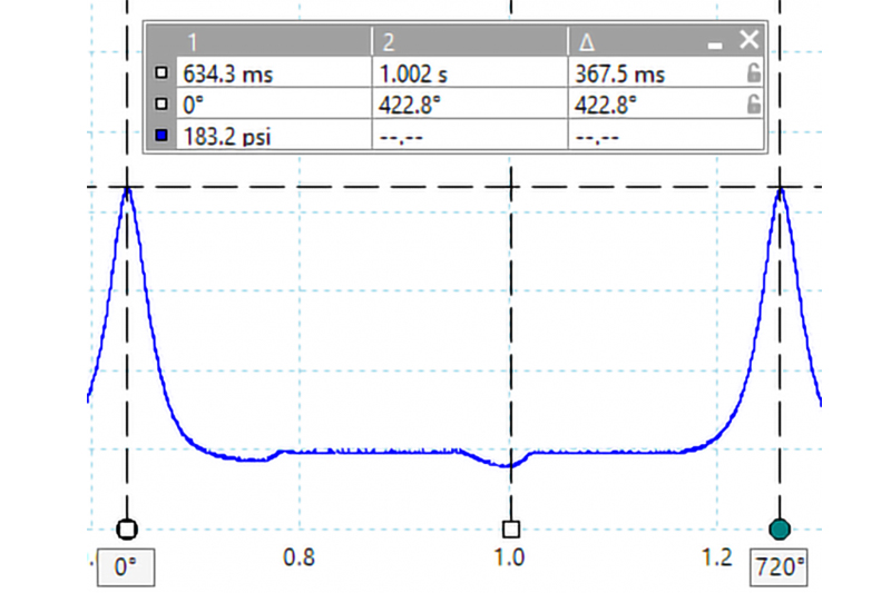
Comparing this to the cylinders in question, we see a peak compression of 183.2psi (12.6 bar) and the intake valve opening 422.8 degrees after TDC (Fig 8).
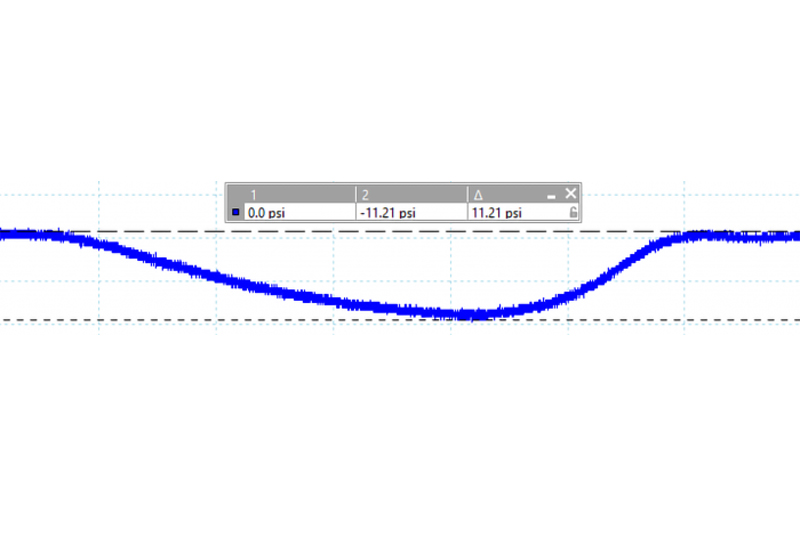
Looking closely at the vacuum pocket, we can see that there is a significant vacuum on the bank 2 cylinders, approximately -11.2psi (Fig 9).
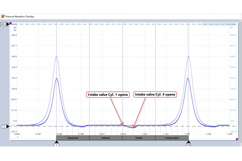
Analysing what the Pico scope showed us, in particular the point at which the intake valve opens, I determined the intake valves on bank 2 were opening 59.9 degrees of crankshaft rotation (29.95 degrees at the camshaft) later than the intake valves on bank 1. This created the large vacuum and the reduced time to fill the cylinders; resulting in rFigure educed compression (Fig 10).

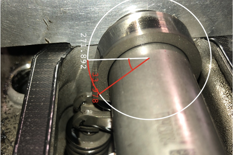
At this point, no major disassembly had been performed and we decided it was time to confirm the cam timing. Upon checking base timing, we confirmed bank 1 was in time and the intake cam on bank 2 was out of time (not the exhaust cam). As you can see in the picture (Fig 11), the intake cam lobe for cylinder 4 (viewed from the rear) should be at a near parallel with the cylinder head surface. A rough estimate shows it is approximately 33.9 degrees off; we estimated 29.95 degrees with the Pico scope.
Now for the root cause of this failure – the intake camshaft on bank 2 drives the high pressure pump via a gear. The intake camshaft on this engine is gear driven by the exhaust camshaft; as a result it spins anticlockwise. The drive gear on the exhaust camshaft is friction welded in place. We suspected that the high pressure pump had become locked up at one point in time, causing the friction weld to slip on the exhaust camshaft, thus resulting in a loss of intake camshaft timing. Once we removed the high pressure pump, we could feel a distinct difference in the effort to turn the pump, compared to a known good pump. Comparing the exhaust camshaft to the new camshaft, we could clearly see the change in relation to the cam lobe and the timing marks on the gear. I should note no gasoline could be detected in the tank, and a sample of the diesel was sent out for analysis to determine the cause of the high pressure pump failure.
Conclusion
The loss of airflow into the engine due to the cam timing was causing a loss of power, causing the EGR dynamic test to fail and setting the air mass codes. This test not only revealed the low compression, but clearly showed us that the root cause was in the mechanical timing. With one test we were able to pinpoint the cause and save countless hours blindly tearing this engine down. It would have been completely plausible for a technician to miss that the cam timing was off upon disassembly as well, resulting in even more time lost.


