
Believe it or not, potentially faulty Air Mass Meters can be checked whilst the component is still fitted to the vehicle. Although it may not be possible to conduct the same extensive testing that AMMs undergo in a dedicated test facility, such as Lucas’s, faulty sensors can still be diagnosed in the garage environment without removing the part from the vehicle. Here’s how:
Testing a traditional AMM using a voltmeter
Many AMMs can be tested on the car using a voltmeter. Typically, AMMs have an analogue output ranging from a possible 0V up to 5V; however, a 5V signal would usually be a saturation point, so you wouldn’t normally see a reading this high.
Bosch-type AMMs generally have a minimum voltage of around 1V; therefore, by using a voltmeter to probe into the sensor wiring at ignition on, the voltmeter should show this value.
TOP TIP: It is always advised to take a ground connection from the battery negative. You then only have to find the output pin on the sensor, which is normally on the end.
Starting the engine will raise the voltage to the level for idle air flow. Then, with some gradual acceleration, you should see the voltage rise in conjunction with the rev count of the engine. The reading will then drop back down as the engine slows back to idle.
A healthy AMM should show a smooth voltage change with no jumps or hesitation. A constant voltage that doesn’t change with acceleration indicates that the AMM is faulty and failure can often be caused by contamination from oil or debris.
TOP TIP: All sensors have a 12V feed, with some having one or two additional 5V inputs. It is worth noting that Siemens-type sensors will sit at a lower ignition voltage than the Bosch – commonly around 0.6V.
Testing a digital AMM using an oscilloscope
Newer digital-type AMMs are not easily checked with a voltmeter and will require the use of an oscilloscope in order to perform a test on the vehicle. Digital sensors have become more commonplace due to their faster reaction times and improved accuracy.
TOP TIP: Digital sensors are often moulded into the measuring tube rather than screwed. The output of digital sensors is viewed with an oscilloscope as a digital waveform. Rather than an increase/decrease of voltage in proportion to airflow, it is the change in frequency of a waveform that is analysed.
Below is an example of the signal at ignition on (Fig 1) and another with air passing through it (Fig 2). The wave gets closer together as the air flow increases on this sensor (i.e. the frequency increases).
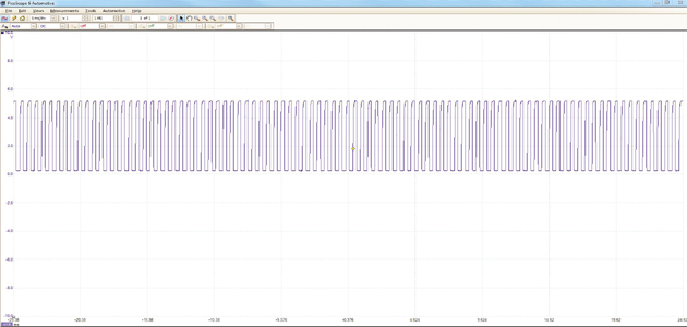
Fig 1
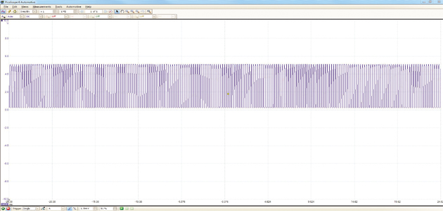
Fig 2
Whilst digital sensors are not as easy to check as the analogue type, it is still possible if you have the correct equipment. As newer vehicles generally have this type of sensor fitted, it is a worthwhile investment.


