
Jim Gilmour, Technical Consultant at Blue Print, takes a look at the function and design of the latest stability system utilised by Mitsubishi.
Electronic stability programmes, by any other name, have been around for over a decade and have contributed greatly to vehicle safety. Much has been written about them, and for the most part, their operation is widely understood by technicians and enthusiasts alike.

Traditional systems
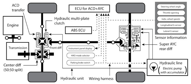
Conventional stability control systems are an extension of ABS and Traction Control and use information from the wheel speed sensors, steering angle sensors and yaw rate sensors (lateral and longitudinal accelerometers), to detect understeer and oversteer close to the limit of the grip of the tyres.
The response is to reduce the tractive effort or torque at the driving wheels and to apply individual brakes to bring the vehicle back in line with the driver’s intensions. It works well and has proved to be reliable; unfortunately it’s a bit like being told off for going too fast!
Is there a better way? Mitsubishi and its customers certainly think so……………..
A different approach
Standing out on its own is the system used on Mitsubishi’s performance All Wheel Drive vehicles, such as the VR4 Gallant and Lancer Evolution. It’s called Active Yaw Control (AYC) and, with the later addition of the Active Centre Differential (ACD), a very different stability control system has been created.
What is Yaw?
The definition of yaw is ‘twisting or oscillating on a vertical axis’, or put more simply, yaw is the difference between the direction a vehicle is facing and the direction it is travelling and occurs under different circumstances.
Straight line acceleration/deceleration
When the driving or braking forces on one side of the vehicle are greater than on the other the vehicle will yaw; this could be caused by differences in the road surface.
Cornering
Yaw can be generated when driving hard into a corner; understeer and oversteer are yaw rotations. Yaw can also be caused by the different forces on the tyres during cornering; the inside tyres have less grip than the outside.
A characteristic of a conventional open differential is that the maximum force applied to the road is limited by the tyre with the least grip, so accelerating and cornering can cause wheel spin on the inner wheel and loss of tractive effort to the outer wheel.
The AYC system goes a long way to remedy these problems. The AYC is designed to transfer torque from the left rear wheel to the right rear wheel and vice versa; this generates a braking torque on one wheel while generating the same amount of driving torque on the other wheel. The AYC system can, therefore, generate a yaw correction – whether it is accelerating or braking.
What does the AYC do?
AYC is part of the all-wheel drive system; up front is a transaxle and housed inside the transmission unit is the centre differential; the two sun gears drive the front differential planet pin and the crown wheel of the transfer box respectively. Early drive systems used a viscous coupling between the transfer box and the front differential, while the later Active Centre Differential (ACD) uses a hydraulically controlled multi-plate clutch. The action of both these devices is to proportion drive to the rear wheels by progressively reducing the centre differential effect.
Take for instance a situation (see Fig 1) where an understeer yaw is generated. This means the centrifugal force generated by the turn causes the front of the vehicle to follow a path of a wider radius than that dictated by the steering mechanism, meaning a tyre slip angle is generated.
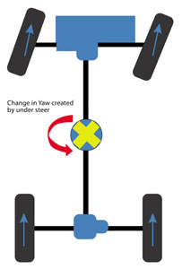 Fig 1
Fig 1
Information from the steering angle sensor, lateral and longitudinal acceleration sensor and the individual wheel speed sensors is monitored and compared with a mapped model of the turn. When understeer occurs, the lateral acceleration is less than what would be generated if no understeer occurred.
To correct this situation the rear AYC differential actuates to increase the tractive effort of the left rear wheel and reduce the tractive effort of the right rear wheel, effectively producing an acceleration on the left wheel and a braking force on the right wheel (see Fig 2).
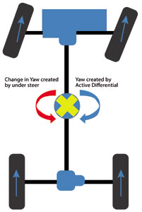
Fig 2
This yaw correction is applied until the vehicle does as it’s told. If, during this operation, there is any slip between the front and rear axles, the central differential effect is reduced by applying modulated hydraulic pressure to the ACD transfer clutch.
How does it work?
The rear AYC unit contains a differential: two clutches and a speed changing gear set; the drive shafts are driven through a conventional differential. Note: later models used an annulus, sun and planet type differential.
The right driveshaft drives the outer part of the clutch set and, with the clutches disengaged (see Fig 3), the rear axle acts conventionally. If a clockwise yaw correction is required, the force generated by the left wheel is increased by engaging the reduction clutch (see Fig 4).

Fig 3 – Mitsubishi Active Yaw Control – Clutch Disengaged
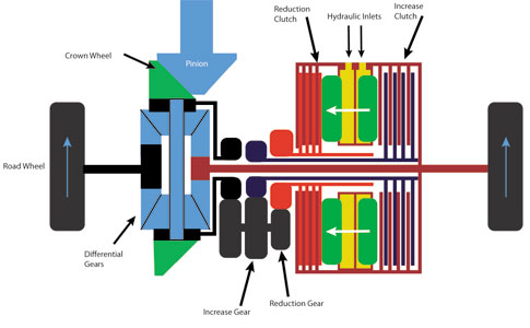
Fig 4 – Mitsubishi Active Yaw Control – Clutch Engaged
Drive from the crown wheel tries to slow down the right wheel through the reduction gear and the torque reaction passes through the differential gears to the left wheel, to try to increase its speed. The amount of torque transfer is governed by the hydraulic pressure in the clutch.
There need only be a very slight increase in speed of the left wheel to create the required yaw correction, the remaining difference in speed is then lost by clutch slip. A counter clockwise yaw correction is achieved by applying pressure to the increase clutch. This causes the right wheel to try to increase in speed and – through the differential – it causes the left wheel to try to slow down.
Hydraulics function
The hydraulics system is a fairly simple affair – an internal gear pump driven by an electric motor pushes hydraulic fluid from a reservoir into an accumulator.
A pressure sensor (pressure switch on earlier models) monitors the pressure at around 15 bars. Directional control valves direct the fluid to the clutches and a proportioning valve modulates the pressure of the clutches.
Seeing things in the flesh
Knowing a little of how this system works is one thing, but experiencing it in action is something else. For this I went to MG Autos in Ripley, Derbyshire; as a business they deal exclusively with Mitsubishi Evo’s and their derivatives, providing everything from servicing to complete rebuilds.
To round up my experience of AYC/ACD, I wanted to monitor the system in action. For this I used the G-Scan and performed a global record on the chassis; this allows me to pick the relevant bits of information after the recording. We set off with the intention of putting the vehicle in a situation where the AYC/ACD system is in operation. This has to be done safely and legally so some of the journey was recorded off road.
Firstly a little explanation of the graphs…
The lateral G sensor gives a value of 2.5 volts when there is no G force. A left force produces a voltage less than 2.5 and a rightward force gives a voltage greater than 2.5.
As can be seen in the data capture (Fig 5 – the point at which the cursor is placed), it indicates a right turn of 52˚ of steering wheel displacement and the vehicle is under acceleration. The graph shows that just before the cursor, the lateral G sensor indicates a voltage closer to 2.5 and, at the cursor, the voltage is lower, indicating a tighter turn. This is the result of the application of the left clutch (reduction) applying more torque to the left driveshaft and a braking torque to the right driveshaft.
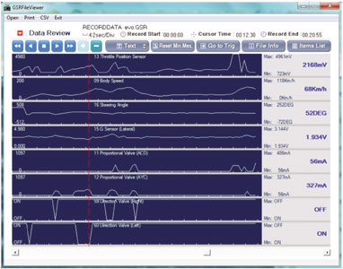
Fig 5
The driving experience is that the vehicle does what it’s told and there was very little to indicate what was happening.
Service/repair issues – the G-Scan can
The G-Scan provides a window into the system which allows the technician to see the operation of the AYC/ACD (Fig 6). Obviously a sophisticated system like this will produce fault codes and, as always, an understanding of how the system operates is a great help.

Fig 6
The AYC/ACD rear transmission unit contains two different fluids, which are contained in three separate areas of the system: EP oil for the final drive and differential, and hydraulic oil (SPF3c), that the clutch plates run in and is used by the high pressure system to apply the clutches. Regular maintenance of these fluids is critical for trouble-free operation.
The AYC/ACD system must be bled every 18,000 miles and this is a function of the GScan for all Evolution vehicles, including the Evolution X. The G-Scan activates the pump and opens the correct valves to allow this to happen. Another excellent feature of the GScan is that the relevant data can be observed during the bleeding operation.


