This month, REPXPERT Alistair Mason replaced the clutch on a 2016 Audi A1, fitted with a 1.6L TDI engine that had covered more than 85,000 miles.
Audi launched the A1 into the UK market back in November 2010, and sales have reached close to 200,000. It is built on Volkswagen’s PQ25 platform, which is also used for the Volkswagen Polo and Seat Ibiza.
Being Audi’s popular Supermini, with a repair time of just five hours and a requirement for only minimal workshop equipment – a two-post vehicle lift, engine support, transmission jack, clutch alignment tool and locking wheel bolt key – this repair is a good one for an independent workshop.
Step-by-step procedure
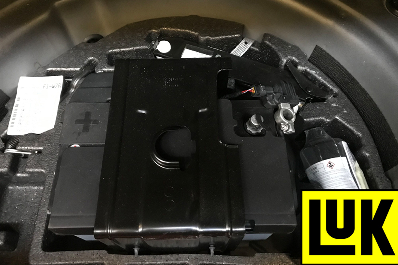
First, place the vehicle on the lift, open the bonnet and boot, and disconnect the negative lead (see below) from the battery in the boot well, but do not close the boot whilst the battery is disconnected. Before proceeding to the engine bay, slacken the front locking wheel bolts and both front hub nuts.
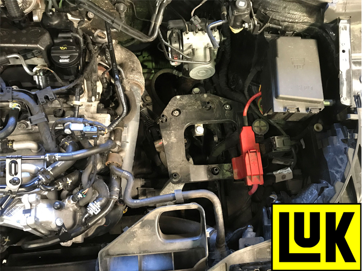
In the engine bay, remove the plastic engine cover and air box assembly (see below), then disconnect the battery connection to the air box carrier, and then remove the carrier itself. That provides good access to the top of the gearbox and bell housing area.
Disconnect the gear change cables, and remove the clutch slave cylinder, leaving the hydraulic pipe connected. Detach the starter motor cable and unscrew the top starter motor bolt, before disconnecting the reverse light switch multiplug and removing the top bell housing bolts.
Next, raise the vehicle lift to gain access to the underside and slacken the inner driveshaft joint bolts, then lower the lift to waist height and remove the front wheels and hub nuts. In addition, remove the N/S plastic wheel arch liner to give better access to the gearbox.
Raise the vehicle lift once more and unscrew both bottom ball joints. The outer driveshaft joints can then be detached from the hub assemblies by pushing the hub assemblies outwards, before undoing the inner driveshaft joint bolts, removing the heat shield for the O/S driveshaft and driveshafts themselves.
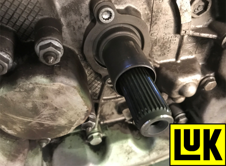
To aid the removal of the gearbox, it is best practice to remove the O/S driveshaft flange from the gearbox that is retained with an Allen bolt in the centre of the flange (see below).
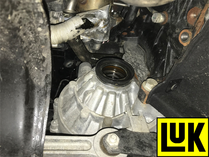
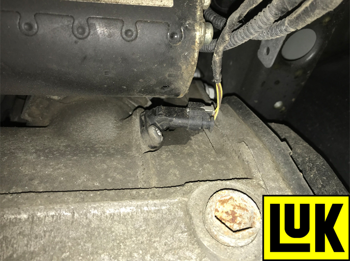
Once removed, unscrew the lower starter motor bolt, remove the starter motor and disconnect the gear recognition multiplug (see below).
Next, detach the lower bell housing bolts, leaving two easily accessible bolts to support the gearbox, before removing the bottom pendulum gearbox mount. Alistair used two transmission jacks to support the engine and gearbox respectively, before using a ladder to gain access to the engine bay and remove the gearbox mounting bolts.
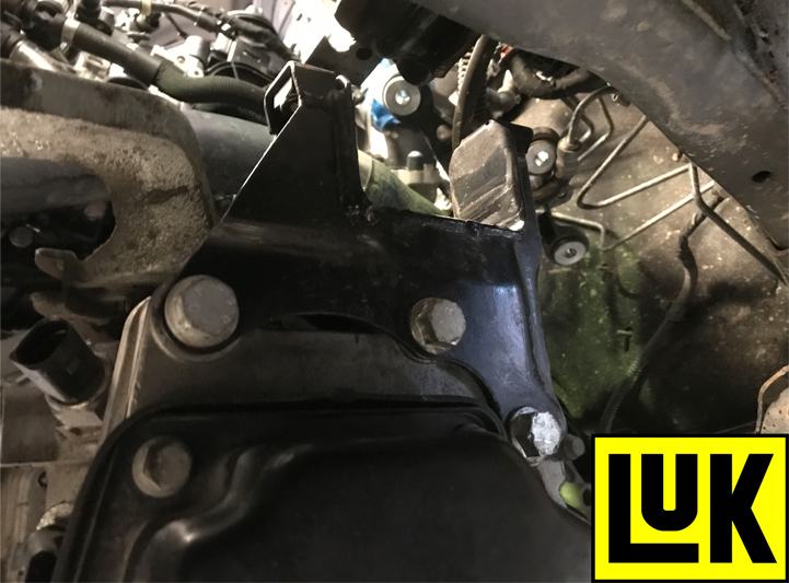
Now, lower the gearbox and engine slightly, removing the gearbox mounting from the gearbox accessed from the N/S wheel arch (see below). Finally, undo the last of the bell housing bolts and ease the gearbox away from the engine. Once clear, lower the transmission jack holding the gearbox and move it to a safe area.
Clutch replacement
Remove the clutch assembly from the flywheel and inspect the back of the engine for any leaks, rectifying if required. Clean the back of the engine and flywheel with brake and clutch dust cleaner, and as a solid flywheel is fitted, remove the glaze from the flywheel face using an Emory cloth and clean again with brake and clutch dust cleaner.
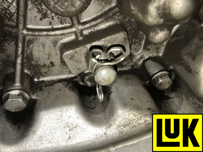
Remove the release bearing from the gearbox and the release arm, closely inspect it for any wear, along with pivot point and release bearing guide tube (see below), replacing if required, and clean the bell housing area with brake and clutch dust cleaner.
Fit the release arm and bearing. If plastic/nylon runs on metal, no lubrication is required; if metal runs on metal, lubrication is required and a light smear of high melting point grease is best practice.
Apply another light smear of high melting point grease to the gearbox input shaft splines, before mounting the new clutch plate onto them. This will confirm the clutch plate is the correct fit, and it will also evenly distribute the lubrication on the input shaft. Remove the clutch plate and wipe any excess grease.
Ensure the clutch plate faces the correct component (see below), and using a universal clutch alignment tool, align it with the clutch pressure plate and secure.
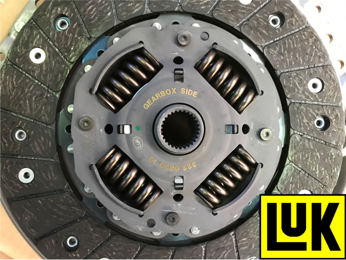
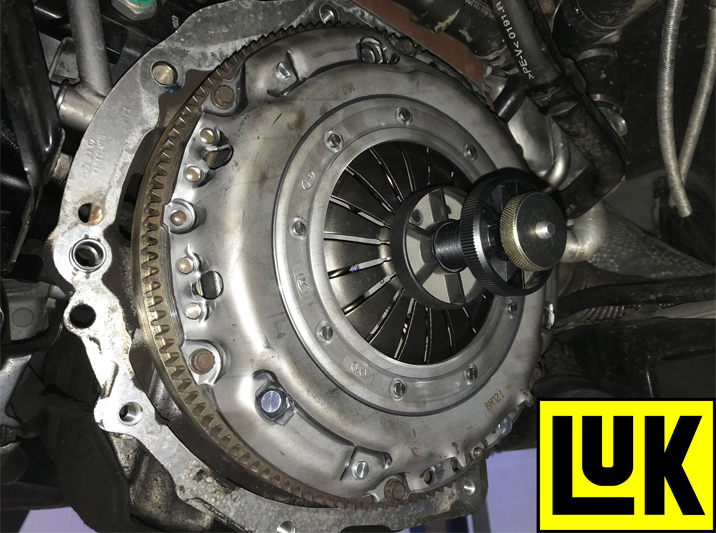
Mount the clutch assembly onto the flywheel (see below), before inserting, tightening and torqueing all clutch bolts evenly and sequentially. Once torqued, remove the clutch alignment tool.
Before refitting the gearbox, ensure all wiring etc. is clear of the bell housing area, so as not to get trapped, while also checking the gearbox alignment dowels are fitted to the engine and that the release mechanism in the gearbox is fitted and functioning correctly.
Gearbox replacement
Place the gearbox on the transmission jack, bring it close to the engine and ease into position, ensuring it locates on the alignment dowels. When in position, fit two easily- accessible bell housing bolts and tighten, refit all other components in reverse order of removal and torque all bolts to the manufacturer’s specification. After the battery lead has been reconnected, reset all electrical consumers.
It is worth nothing that new hub nuts will be required, if the locking tabs break off during removal. Finally, as always, carry out a road test to ensure a quality repair.


