![]()
The Ford Transit has been around since 1953 but this early Transit was rarely seen in the UK. The Ford Transit we have come to love was introduced in 1965 and was known by many as the Mark 1. With over 6,000,000 vehicles built since its introduction we have all seen them in our workshops. In this article we are going to look at changing the front wheel bearing on a Next Generation Transit which was launched in 2000 and ran until 2006; although the current Transit is very similar.
This particular Transit was a rear wheel drive model however, the procedure for changing the bearing on front wheel drive models is very similar. The manufacturer’s recommended repair time of 0.9 hours is easily achieved with the help of this guide from FAG.
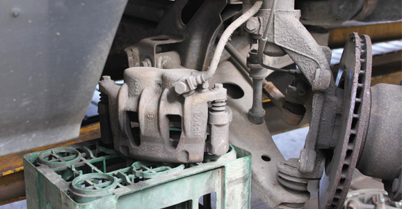
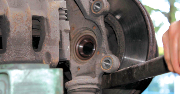
A four-post ramp was used to change the wheel bearing in this example however, a good two-post ramp or axle stands could just as easily be used. The only special tools required are a torque wrench and a suitable press. The old bearing will also have to be pulled off the hub with the use of a special puller (Ford part number 15-092 and 15-091). After determining which bearing is to be replaced, safely raise the wheel off the ground and remove. The brake caliper is removed next. To do this gently squeeze the piston back slightly and then undo the two securing bolts.
Carefully place the caliper clear to one side, taking care not to put strain on the brake hose (see picture below).
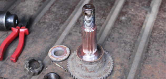
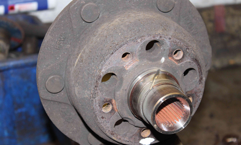
Remove the split pin and castellated pressing from the centre hub nut and then undo the nut and remove the washer. On the rear wheel drive models the splined shaft is very short; the purpose of the shaft is to allow for a phonic ring for the ABS sensor (see picture below) and this can easily be removed from the hub by using a copper hammer to gently drift it out. On front wheel drive models the drive shaft will have to be completely removed from the hub.
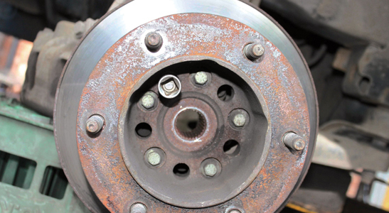
To do this separate the hub carrier from the lower suspension arm and then with the aid of a copper hammer gently drift the driveshaft out. Next the five torx bolts securing the hub to the carrier will have to be removed. To do this align the holes in the brake disc to the bolts securing the hub to the hub carrier (pictured below) and then with a 50 torx socket and extension remove the bolts (a good quality torx socket is recommended, if the heads of the bolt get rounded off it will be extremely difficult to remove them due to their position and they will have to be drilled out).
The hub assembly can now be removed – it may be necessary to gently prise the hub from the back (pictured below). Separate the brake disc from the hub assembly.
Remove the bearing
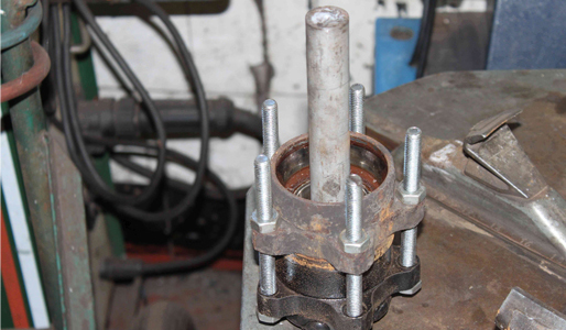
The bearing can now be removed from the hub. To do this, attach the special tool to the top of the bearing and then wind the bearing off the hub. In this example we made our own
tool from an old bearing with a strong steel pipe securely welded in the centre (pictured below).
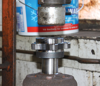
Then with a press we pushed the bearing off (the bearing will fit either way up so make a note of the fitting position of the old one first). The inner race of the bearing will then have to be removed from the hub. Because there is nowhere to attach a puller securely, tap the bearing needle roller bearing and cage off and then with a die grinder carefully cut part way through the inner race just enough to weaken it, taking care not to damage the hub (pictured below) – then gently tap the race off.
Note: using a blunt air chisel is a nice controlled way of removing the inner race without causing damage.
Making sure the bearing assembly is the correct way round, push the bearing back on to the hub with the press by applying pressure to the inner race (pictured below).
Note: check the length of the new bearing assembly against the old one as there are two different lengths.
Clean the contact surface between the hub and the disc. The brake disc can now be refitted to the hub. Clean the hub locating hole on the hub carrier. Whilst holding the hub in place take care to align the holes then secure the hub with the new bolts provided, tightening them evenly and sequentialy to the manufacturer’s 53Nm. On rear wheel drive models the splined shaft can now be reinserted.
On front wheel drive models re-fit the drive shaft and re-attach the hub carrier to the lower suspension arm. Fit the new retaining washer and nut but don’t tighten fully just yet. Next the brake calliper is refitted and the bolts tightened to 175Nm (because the brake calliper has been removed it is advisable to pump the brake pedal a couple of times to allow the piston to return to its operational position). Re-fit the front wheel and then lower the vehicle back to the ground.
The hub nut can now be tightened in two stages:
Stage 1 – tighten the nut to 250Nm;
Stage 2 – rotate the hub several times then tighten to 420Nm.
Check the hub now turns freely and fit the castellated pressing and new split pin in place.
Find out how to replace the front wheel bearing on a Toyota Corolla by clicking here


