If you were to ask five different technicians what diagnostics is, it’s likely that you’ll get a number of different answers. Some will consider that the diagnostics are done by a scan tool, some will say that diagnostics are achieved by the oscilloscope or multimeter and others will say the technician is responsible for diagnostics. I tend to think of diagnostics as the detection, through data gathering and analysis, of the root cause of the symptom affecting the normal behaviour of the system. It’s the application of the relevant tools, training, experience, information and brainpower to come up with the cause of the fault.
My view differs to a large number of technicians in that the diagnosis and the fix are definitely two separate and distinctly different processes. I charge for performing tests, analysing the results and presenting my findings to the customer. Some complex, multilayered faults may need repair or replacement on the way to the ultimate diagnosis, but fitting and fixing are definitely separate to diagnosing the root cause.
Diagnostics – a specialism
The level of investment required (time and money) to become highly proficient in diagnostics leads me to think that this aspect of the trade will further develop into a specialism. The problem is that electronics and technology are becoming a more intrinsic part of the motor vehicle, and true diagnostics will soon be a skill required within every prosperous motor repair business. We can’t blame customers for not understanding the difference between fault code retrieval and proper diagnostics but making clear that separation of the diagnosis from the fix will deliver your business both financial and customer service benefits in the long run.
The example job I have chosen to discuss here is a 2006 Ford Focus TDCi. Running concerns on these vehicles strike fear into the heart of many technicians. My sample vehicle exhibited interesting and challenging behaviour (a phrase I’ve borrowed from the ‘Super Nanny’ who makes references to unruly children using the same words). Our problem child starts relatively well, runs with a misfire for the first 4 or 5 minutes and then drives quite well, until the next cold start. The vehicle has been to several repair facilities, has got a dubious repair history and is sporting a host of new components, including a set of new genuine injectors.
Part of the discipline of diagnostics is not presupposing the cause, but rather to base conclusions on evidence gathered during the testing phase. Linked with back to basics, the phrase: “say what you see” helps me to focus on the problem.
Say what you see
I see a cold diesel engine running with a misfire. Cold engines generally produce lower compression. It is critical for the diesel engine to have sufficient compression to generate heat to burn the fuel. The Focus is generating clouds of grey/white smoke, vaporised fuel unburnt fuel, so it is likely that I have a compression issue. My next challenge is to perform a compression test to confirm my assumption. I don’t relish the thought of snapping off a glow plug, or having to rem ove injectors to get a compression reading, so I’ll use the relative compression test using the high range current clamp. Because the sample is relatively slow, I don’t really need a multi hundred pound mega fancy-clamp, my old multimeter clamp will do just fine (pictured, left).
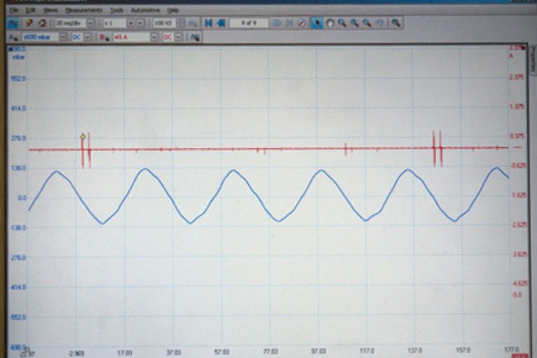
The resultant waveform, taken with the Picoscope, shows that there is definitely one cylinder down on compression. The only problem is working out which one, and why. This is a Piezo type of injector system, which makes it difficult to get a reference trigger to synchronise and define the exact cylinder. It is possible to do this using a dummy injector, but in this case, seeing one compression down is good enough. I can use my scan tool data stream and observe the injector correction factor to identify which cylinder is contributing the least. In this case, cylinder 3 has a positive deviation, meaning that the ECU is trying to speed the cylinder up, which suggests that the ECU considers it to be running too slowly, due, once again, to the compression issue.
Play with the breather system
My next task is to work out why the compression is too low. The likely causes are either piston rings, valves, leakage through injector seal/glow plug or a bent con rod. I can use a pressure transducer, allied to the oscilloscope, to check the integrity of these items (this is something we focus on in our ‘One Day Advanced Oscilloscope’ training course). First, because it is easiest, we can place the pressure transducer into the dipstick tube. If compression can ‘blow-by’ the rings it will cause a positive pressure deviation
(pressurisation) in the sump. You may need to play around with the breather system, depending on the vehicle under test, to achieve a decent reading.
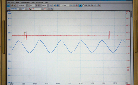
The capture below shows the sump pressure reading. It is obvious to see that all of the pressure pulses are generally even, so there is no supporting evidence of a problem with the piston rings.

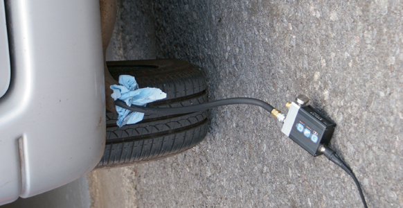
We can also use the pressure transducer in the exhaust pipe, using a piece of ‘calibrated’ rag (see example, below) to generate a small amount of back pressure which will aid the analysis. Once again, we are looking for an anomaly, or difference, in the pressure pulses. In our case, the pressure transducer in the exhaust pipe is of little use, as we have large fluctuations in the pressure pulses due to the misfire caused by the compression problem. An alternative strategy in this case is to place the pressure transducer into the intake manifold and use a blanking place across the manifold intake to create a vacuum.

If the valve doesn’t seal correctly, a positive pulse will be seen in the intake when No 3 reaches TDC, as the compression pressure tries to escape into the intake manifold. If the exhaust valve is at fault, we will see a lack of vacuum when No 3 is on the intake stroke, as the cylinder will try to fill via the non sealing exhaust valve.
Improvised height gauge
Our tests, therefore, show us that none of the compressed air is leaking from the cylinder due to wear in the valves or piston rings and so the lack of compression has to be due to another factor. The injector seals are fine, as is the seal on the glow plug. What else is left? Perhaps the connecting rod has been bent? In order to diagnose this, the injectors will have to be removed. As they have been replaced fairly recently, they should come out relatively easily, which they do.
Using an improvised height gauge, a length of welding rod cut to length and a straight edge, I put cylinders 2 and 3 at TDC. I carefully placed the rod down the injector hole until it touched the piston top and measured the protrusion. Cylinder 3 was around 4mm lower than its mate cylinder. I measured no 1 and no 4 as comparisons and they were at the same height as cylinder 2. Therefore, the data confirmed that cylinder three was lacking compression due to a piston height deviation (probably caused by a bent rod). What was certain was that the engine will have to come apart for a visual inspection.
In summary, the job was broken down into several distinct steps. Firstly we reviewed the scant repair history (new injectors and other parts). Then we analysed the behaviour, and took note of what happened and when, clarifying the exact nature of the symptom (misfire when cold, grey/white smoke, ok when warm – possible compression problem). We considered a lack of compression as a possibility and chose to measure and analyse the compression data. This verified a headline problem, but we still needed to uncover the detail. We ruled out some of the causes using the vacuum transducer, and were left with only one option. We removed the injectors and confirmed the assumption.


