Pico technician Steve Smith puts his EV diagnostic skills to the test with a BMW i3 that is refusing to switch to ‘Ready Mode’ and is displaying a drivetrain error message.
Vehicle information
Manufacturer: BMW
Model: i3, 94Ah (Full EV)
Year: 2016
Model code: I01
Engine code: 1B1
Transmission: Single speed with electric parking lock
Mileage: 34,783 miles
Failed part: Wiring harness failure
Customer’s description
The customer reported that when they tried to switch on and power the vehicle to ‘Ready Mode’, the instrument panel displayed a ‘drivetrain error warning’ and the vehicle could not be driven.
Technical description
Verifying the customer complaint is an essential step in the diagnostic process, but it is quite often a time-consuming task without success. On this occasion, the customer complaint was bang on as the instrument panel and the iDrive displays both indicated a drivetrain error accompanied with the message: ‘It is not possible to continue journey’.
Note: It was not possible to shift the vehicle from ‘Park’ with the transmission select switch, and while the ignition could be turned on to illuminate the instrument panel and associated warning lights, the high-voltage (HV) contactors were not energised (i.e. the HV system appeared inoperative). In addition to the symptoms above, the vehicle would not allow charging to commence when connected to an EVSE point (electric vehicle supply equipment).
This video demonstrates the symptoms described above.
Diagnosis: Day 1
With the customer complaint verified, we confirmed the vehicle’s ID and specification. Confirmation of specification is of the utmost importance when it comes to diagnosis as there is often a temptation for customers to modify their vehicle with fashionable accessories that lack the fundamental quality control and engineering that was originally intended for the vehicle. The customer confirmed that no such accessories had been installed.
The customer interview followed the four targeted open question principle below to establish fact from fiction:
- How long has the problem been evident?
The fault occurred without any warning (the vehicle was then recovered to the workshop). - When did you first notice the problem?
The symptom occurred once, leaving the vehicle immobilised and requiring recovery. - Has any work been carried out on the vehicle recently?
No. - When do you experience the problem?
No driving pattern required. One day this vehicle was fine, the next day it would not power up!
Quite often the customer interview leads to a probable diagnosis, but I think you will agree that in this case, after receiving the responses above, there was literally nothing to go on!
The basic inspection confirmed no fluid leakages, no visible signs of damage to hoses, connections, wiring harnesses, or that favourite discovery: accident repair.
A vehicle scan of all onboard control units revealed 17 fault codes, which we saved and erased. We cycled the ignition from ON, to OFF, to ON and made an attempt to power the vehicle to ‘Ready Mode’. Once again, the drivetrain error message was displayed.
Using this technique ensures that the remaining codes are relevant to the fault condition and not codes introduced by previous diagnosis.
A rescan of the vehicle revealed the following six faults codes:
Engine control
- 21E96F Ready for starting signal: Signal missing
HV batt.charge control 4.0:
- CE5402 Message: High-voltage battery 2 data: Missing message
- 21E687 Voltage Terminal 30 C: Crash detected
- CE5406 Message: High-voltage battery 1 data: Missing message
- CE5403 Communication with HV battery control unit: Missing message
Informat. electronics 4.2:
- B7F805 L-band antenna: Open circuit in wiring
To interpret the fault codes we obtained during the vehicle scan, we had to decode the terminology as universal scan tools often use differing descriptions for OE system components. This is a typical hurdle to overcome, which we have demonstrated and discussed in previous case studies.
For example:
- ‘Engine control’ refers to Electric Digital Motor Electronics – EDME (BMW terminology)
- ‘HV batt.charge control 4.0’ refers to Battery ECU – SME (BMW terminology)
While this may not seem relevant at this stage of the diagnosis, we needed to interpret the abbreviations used in the BMW wiring diagrams against the component descriptions, fault codes and data we obtained from the scan tool. I guess you could liken this to the translation of languages, i.e. the language used by the scan tool and the language used in BMW technical documentation.
Which fault code should we follow and why?
Given that we were using a generic scan tool, we did not have access to the occurrence order of the fault codes.
Based on the fault code descriptions, the following was my interpretation:
SME fault code ‘21E687 Voltage Terminal 30C: Crash detected’ would be the primary fault code to pursue as ‘Crash’ takes priority over everything else!
With a ‘Crash detected’ fault code, it is no surprise that the EDME is returning ‘21E96F Ready for starting signal: Signal missing’. With a crash detected, the HV system would have been shut down immediately.
Likewise, the SME is also returning:
- CE5402 Message: High-voltage battery 2 data: Missing message
- CE5403 Communication with HV battery control unit: Missing message
- CE5406 Message: High-voltage battery 1 data: Missing message
Informat. electronics 4.2:
■ ‘B7F805 L-band antenna: Open circuit in wiring’ is not relevant to our diagnosis
Let’s be honest here. How difficult would it be to chase ‘Missing messages’ compared to the Terminal 30 C voltage at the SME? For this reason, we left the CE5402, CE5403 and CE54006 codes alone for now. At this stage, my mind is running riot thinking this could be a crash repaired vehicle even though the basic inspection revealed no accident repair work.
Before diving in, at this point it is paramount to take a step back and check for technical bulletins (recalls and campaigns, etc.). The best possible way to qualify the presence of known issues and fixes is to use the manufacturer’s technical portal combined with the vehicle chassis number.
While this may seem obvious, there are a number of avenues to obtain free technical bulletins and so called ‘fixes’. I have experienced that while the entire description of such obtained data matches the exact symptom and fault code you have obtained, the bulletin may well be for other markets, i.e. not applicable to the UK. Please don’t fall into this trap as I have done with other vehicles in the past.
In this case, there were no such bulletins to take into consideration.
Possible causes
- Accident repaired vehicle with immobilising crash data
- Crash sensing circuit component error
- Crash sensing circuit error
The action plan
The action plan was, as usual, predominantly governed by accessibility, probability and cost. Based on the acquired scan data, the fault code 21E687 was very descriptive about the voltage level at Terminal 30 C of the SME. The action plan, therefore, focused on the integrity of Terminal 30 C and the associated circuit.
Recap
- The vehicle failed to power up to ‘Ready Mode’
- The vehicle failed to charge from EVSE
- A drivetrain error message was reported on the instrument panel
- There were multiple fault codes stored with the SME reporting ‘Crash detected’
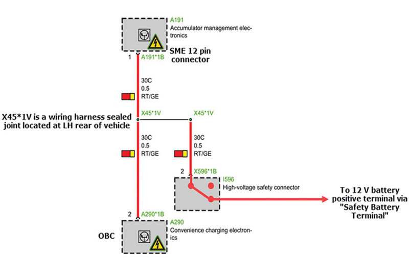
Circuit 30 C can be seen below in the wiring diagram (Fig 1/main image – supplied by ALLDATA). I have added a number of annotations to help with my interpretation of the BMW terminology.
For example:
- I understand ‘Convenience charging electronics’as the On-Board Charger (OBC)
- X45*1V is a sealed joint within the wiring harness under the vehicle on the left-hand rear side
Note: The high-voltage safety connector in Fig 1/main image is responsible for switching off the HV electrical system to carry out repair and maintenance work. Please refer to the workshop manual and make sure that the relevant procedure is followed by suitably qualified personnel.
If the high-voltage safety connector is open, the 12V supply to Terminal 30 C at the SME and OBC will be removed (30 C now at 0V) and so the HV system is switched off until the power supply to Terminal 30 C is reestablished.
The high-voltage safety connector is linked directly to the 12V battery positive post via a Safety Battery Terminal, which includes a pyrotechnic device designed to break the connection between the 12V battery and the high-voltage safety connector (triggered by the Airbag crash module) in the event of an accident.
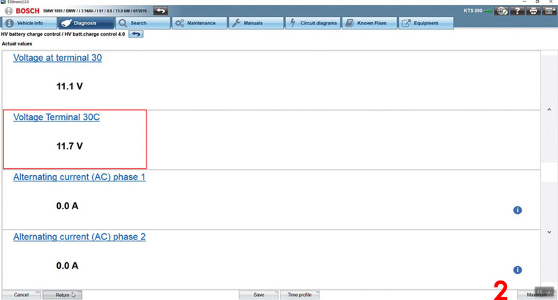
In Fig 2, you can see the voltage present at Terminal 30 C of the SME, as reported by the scan tool.
However, Fig 3 shows the Terminal 30 C voltage measured with PicoScope at connector A191*B pin 1 (Red/Yellow wire) of the SME.
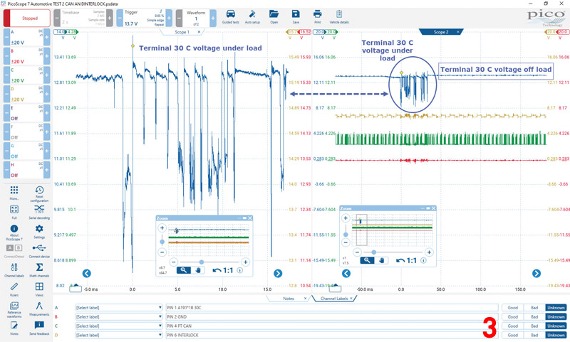
We can immediately see a concerning issue with the voltage at Terminal 30 C of the SME when we applied electrical load in the form of attempting to power the vehicle to ‘Ready Mode’.
The load applied would be in the form of the HV battery contactors attempting to connect the HV battery to the vehicle HV system. However, as soon as Terminal 30 C voltage at the SME drops below a predetermined threshold, the contactors would be de-energised immediately.
Let me share a tip on using the scope to monitor and capture voltage dropout. Select a slow timeframe (2 s/div) whereby the waveform is drawn across the screen in ‘realtime’, which can be interpreted by the human eye during events such as ignition ON/OFF or wiggle testing.
While the scope can also be used to capture these events at ultra-speed with triggers, it is difficult to interpret and link waveforms to events, such as wiggle tests that are only displayed on screen for a split second. In such cases, the user would then have to scroll back through the waveform buffer to find an event that may or may not be linked to ignition ON/OFF or wiggle testing.
The PicoScope capture provided sufficient evidence to further test the integrity of the crash sensing circuit (30 C), unlike the value displayed by the scan tool that may lead you to believe Terminal 30 C at the SME is OK (the refresh rate of the scan tool is too slow to capture the voltage drop).
So far, we had confirmed that Terminal 30 C voltage at the SME is unstable under load. Based on this knowledge, we needed to qualify the integrity of the 30 C circuit at the high-voltage safety connector. We were on for another day of diagnosis…
Read the next issue of PMM to find out what happened on day two of diagnosis and how it led to Steve’s final conclusion.


