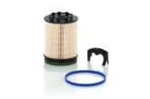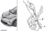
Along with many other engine components that are critical to economy and the environment, filter technology is constantly evolving to keep pace with the twin demands of EU legislation and vehicle design and packaging.

Warning signs
The latest Euro 6 emissions standard comes into force in 2014, and vehicles meeting this standard are already on the market. To comply, the complete air intake system – including the air filter – must work in harmony; not only to meet emission levels but also to prevent the engine warning lamp illuminating and the vehicle entering ‘limp’ mode.
Some Volkswagen models are now programmed to give a fault code of “incorrect air filter” if the flow characteristics are incorrect, so service technicians who mistakenly believe that a low quality air filter will perform as well as the correct OE quality part could be making a big mistake.
The air filter has often been seen as a somewhat poor relation to other automotive filters such as the oil filter, but that is no longer the case. Although the air filter used in the latest Ford Focus, Fiesta, Kuga and other models looks visually the same as the earlier part, the new filter incorporates a wealth of engineering changes. The earlier part, sadly, will simply not perform to the correct standard.
Engineering expertise
In a perfectly designed air intake system, the mass air flow sensor would be mounted around 50mm from the air filter, in a straight inlet tract with a bell mouth entry, to smooth air flow, but in many modern vehicles it is not possible to achieve this ideal design due to the location of the parts and the vehicle’s design.
Consequently, the design and repeatable flow characteristics of the air filter become vitally important. The Ford filter had to be completely re-engineered to ensure that all parameters could be met over the life of the filter. Particular attention was paid to the number of pleats in the filter, their spacing and the embossing of the paper, with a new embossing design, updated specification and tighter tolerances on pleat spacing.
The ‘dead’ pleat – where the paper of the element is joined – was also found to have a detrimental effect on the flow performance of the filter. To counteract this and get accurate air flow measurements, it was important to ensure that the pleat is always located in the same position in the airbox, where it would cause minimum disruption to the air flow.
Problem solvers
Engineers at MAHLE solved this problem by fitting a locating ‘tang’ on the filter (now a MAHLE patent), which locates in the airbox when fitted. This ensures that the filter is always orientated correctly. The internal support cage of the filter was also redesigned and production controls put in place to ensure that one of the uprights is always in line with the ‘dead’ pleat.
Only when all of this is in place is the air filter able to condition the airflow before it passes over the MAF sensor, allowing for accurate air flow readings for the life of the filter across multiple different vehicle applications. The air filter has to perform all of these tasks whilst being resistant to the increasingly hostile under-bonnet environment of extreme temperature variations, vibration and moisture.

