
It’s hard to believe that the Volkswagen Transporter was first introduced way back in 1950; amazingly that’s over 60 years of production. During this lengthy span the Transporter has evolved many times, starting with the very first T1 ‘split screen’ models to the more recent and technologically advanced T5.
The older vintage models attract a massive and dedicated fan base in the UK and with over 63,915 models now sold from 2003 until today, the newer T5 is proving every bit a popular as its vintage predecessors. A clutch replacement on the Transporter can be a little tricky but with guidance of LuK the whole process will become much easier.
Nothing out of the ordinary is needed to complete the job, the only special tools required are a transmission jack, an engine support beam and a long axle stand. A four-post ramp was used in this example, however a two-post ramp may also be suitable. For safety reasons it’s considered best practice to disconnect the battery earth lead before commencing work. If the vehicle has alloy wheels it may be fitted with anti-theft wheel bolts, so make sure you have the key before you start.
Open the bonnet, unclip the nearside plastic battery cover and disconnect the two battery terminals. Release the battery clamp and lift the battery out of the engine bay. Undo the two screws securing the coolant header tank and safely stow this to one side. Unclip the wiring harness from the plastic battery surround then undo the two bolts securing the surround (pictured below) and lift it out.
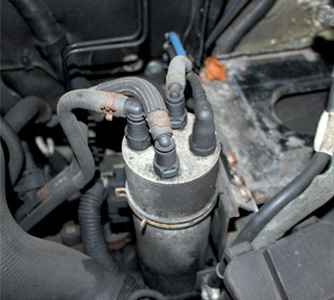
Remove the four quick release hoses (pictured below) from the top of the fuel filter and lift it out by releasing the clamp ring with a pair of pliers.
Release the rubber air inlet pipe at both ends by pulling out the relevant clips on the hose. Once these clips are released the hose will dislodge when pulled. Unplug the mass airflow sensor and lift the whole assembly out.
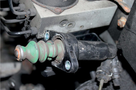
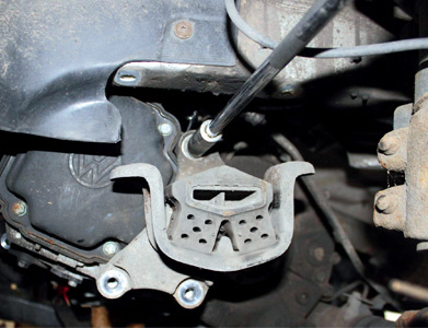
Release the gear linkage cables and lift them off. Remove the starter motor electrical connections and unbolt the motor. Release the slave cylinder (pictured below) and the two gear linkage bracket bolts that you can get to.
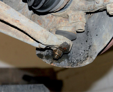
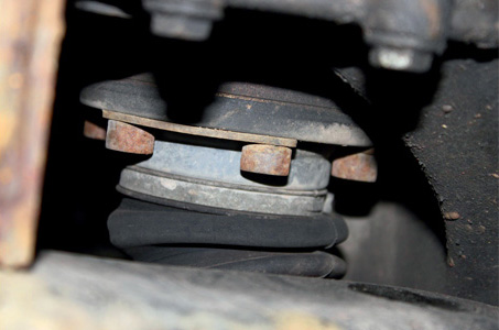
Set up the engine support beam and undo the upper bell housing bolts. Remove the road wheels and the hub nuts on both sides. Remove the large plastic undertray and lower it down carefully. Unplug the reverse light switch and release both front lower suspension arms (pictured below).
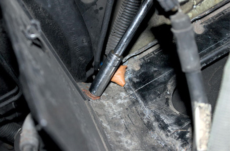
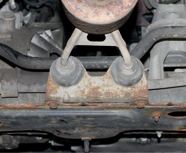
Remove the last bolt holding the gear linkage bracket and remove it. Undo the two bolts securing the offside driveshaft support and remove the shaft. Undo and release the nearside driveshaft by undoing the bolts (pictured below) and lift it out. Undo the rear engine mount steady bar and remove it.
Undo the four bolts securing the steering rack to the subframe and release the engine mounting attached to the subframe by undoing the single bolt. While supporting the subframe, undo the bolts securing it and lower it down to gain access.
Undo the two exhaust bracket support bolts (pictured immediately below) followed by the three bolts securing the gearbox support bracket (pictured second below). Remove the lower bell-housing bolts and lower the gearbox to the floor carefully.
With the clutch removed, check the dual mass flywheel (DMF) for signs of heat stress and evidence of grease loss. The DMF should also be tested for freeplay and rock between the primary and secondary masses (LuK tool number 400 0080 10 is specifically designed for this purpose on all LuK manufactured DMFs). Full instructions and tolerance data for all LuK DMFs are contained on a CD which comes with this special tool.
Clean the first motion shaft splines and any debris from the bell housing (especially important when a release bearing has failed). Remember, if the bearing or sleeve is made of plastic there is no need for lubrication. If both parts are metal then a high melting point grease should be used and not copper-based products. Put a small dab of grease on the first motion shaft splines and make sure the new driven plate slides freely back and forth. This not only spreads the grease evenly but also makes sure you have the correct kit.
Wipe any excess grease off the shaft and driven plate hub. Using a universal alignment tool and checking the driven plate is the correct way round (note “Getriebe Seite” is German for “Gearbox Side”), the clutch can be bolted to the flywheel evenly and sequentially. Before fitting the gearbox make sure the locating dowels are in place and not damaged. Refit any that have become dislodged and refit the gearbox. Make sure the gearbox bell housing bolts are secured before lowering the jack.
Refitting is the reverse of the removal.


