
The Sunderland built Nissan Primera – in its third generation (P12) guise– has been with us since 2002, where it quickly forged a reputation as a quality and reliable car. These continued to be sold in the UK until production came to an end in 2008 but they are still proving a popular vehicle in the UK aftermarket, with over 40,000 vehicles on the road.
No special tools are required for the procedure. The only additional tools needed are a transmission jack, an engine support cradle and a long axle stand. A two-post ramp was used in this example however it is recommended that a four-post ramp is not used as it may not provide enough clearance. For the sake of safety it’s considered best practice to disconnect the battery earth lead before commencing work. If the vehicle has alloy wheels it may be fitted with anti-theft wheel bolts, so make sure you have the key before you start.
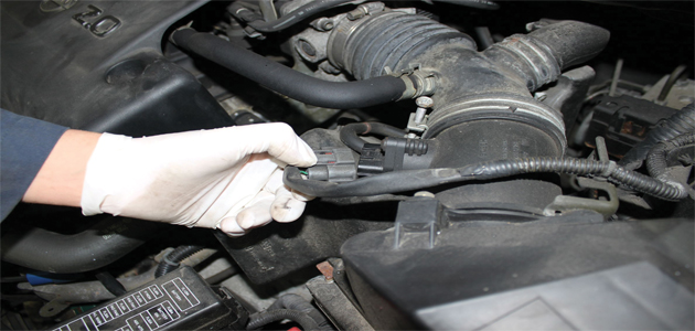
Open the bonnet and disconnect the battery earth lead. Disconnect the Mass Air Flow (MAF) sensor (pictured below) and unclip the harness attached to the air filter housing.
Disconnect the large breather pipe connected to the housing and slacken the jubilee clip attaching it to the inlet manifold. Undo the single bolt securing the housing to the vehicle body and disconnect the small breather connecting the housing and the gearbox. Lift out the complete air filter housing assembly.
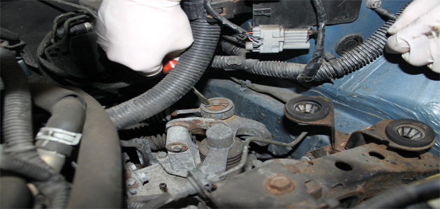
Remove the gear selector cables by removing the ‘R’ clips (pictured below) and the washers securing them in place.
Lift off the cables and disconnect the reverse light switch. Remove the two bolts securing the slave cylinder (pictured below) to the gearbox and stow it to one side.
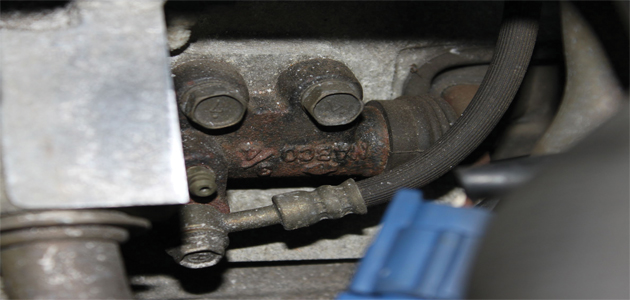
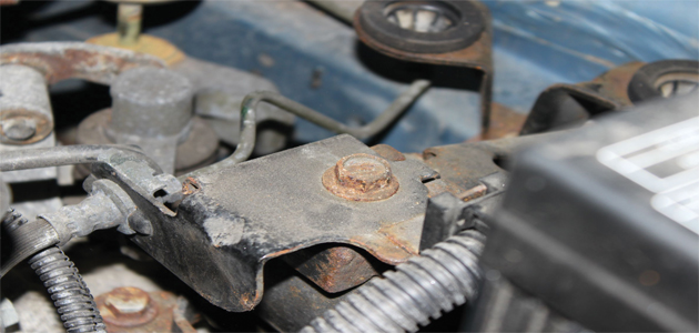
Remove the two bolts securing the harness support brackets on top of the gearbox and the support bracket securing the hydraulic pipe (pictured below) and stow them to one side. Undo the top starter motor bolt and the accessible top bell housing bolts.
Fit the engine support beam and remove the four bolts securing the gearbox mounting bracket to the gearbox.
On the up
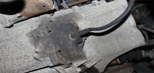
Raise the vehicle to a comfortable working height and remove both front wheels and the nearside wheel arch liner. Raise the ramp further and remove the engine under tray. Disconnect the earth connection (pictured below) on the gearbox and drain the gearbox oil, remembering to replace the drain plug afterwards.
Remove the bolts securing the rear cross member to the vehicle chassis and carefully lower it to the floor. Remove the bolts securing the central support to the engine and gearbox and lower the complete assembly to the floor. Some variations have been found to not have sufficient clearance for the bolts to be removed due to the position of the exhaust downpipe. In these cases it may be necessary to lower the downpipe out of the way so that the bolts can be removed.
and the lower wishbone pivot support brackets. To avoid damaging the brake calliper pipe unbolt the supporting bracket (pictured below).
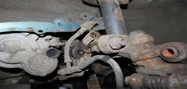
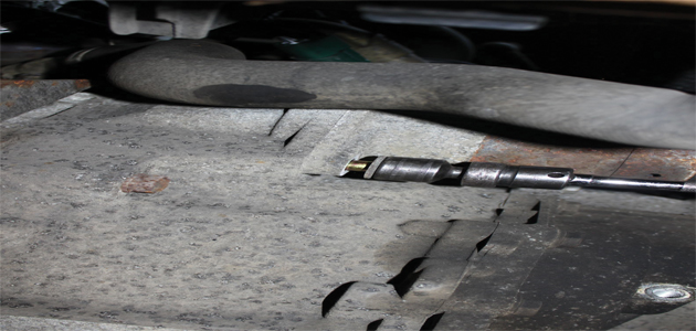
Disconnect the anti-roll bar link joint and lower the wishbone, taking care not to damage the ABS sensor wire. With care, pop the nearside drive shaft out of the gearbox and stow it to one side. On the offside driveshaft remove the driveshaft support bracket and the closing plates on the engine facing side of the gearbox. With care, extract the driveshaft out of the gearbox and stow it to one side. Undo the final bolt on the starter motor (pictured below) and with the aid of the transmission jack remove the remaining bell housing bolts. The gearbox can now be carefully lowered to the floor.
DMF best practice
Once the transmission has been removed check the Dual Mass Flywheel (DMF) for signs of heat stress (cracks and blueing) and evidence of excessive grease loss (deposits on the bell housing). The DMF should also be tested for rotational free-play and rock between the primary and secondary masses – LuK tool number 400 0080 10 is specifically designed for this purpose on all LuK manufactured DMFs. Full instructions and tolerance data for all LuK DMFs are contained on a CD which comes with this special tool.
Clean the first motion shaft splines and any debris from the bell housing (especially important when a release bearing has failed). Ensure that the release bearing is always replaced if the clutch and/or DMF are worn out. Put a small dab of high melting point grease (not a copper-based product) on the first motion shaft splines and make sure the new driven plate slides freely back and forth. This not only spreads the grease evenly but also makes sure you have the correct kit. Wipe any excess grease off the shaft and the driven plate hub. Using a universal alignment tool and checking the driven plate is the correct way round (note “Getriebe Seite” is German for “Gearbox Side”) the clutch can be bolted to the flywheel evenly and sequentially.
Before fitting the gearbox make sure the locating dowels are in place and not damaged. Refit any that have become dislodged and refit the gearbox. Make sure the gearbox bell housing bolts are secured before lowering the jack. Refitting is the reverse of the removal and make sure the manufacturer’s recommended torque settings are used.


