
The Land Rover Freelander was first released back in 1997 and has gone on to sell over 190,000 vehicles in the UK alone. As a result of this popularity over the years there are now plenty of these vehicles in the UK aftermarket and chances are you may be seeing a Freelander in your workshop sometime soon.
A clutch replacement on the Freelander can be a little tricky but with the guidance of LuK the whole process will become much clearer. Nothing out of the ordinary is needed to complete the job, the only special tools required are an engine support beam, transmission jack and a long axle stand. A two-post ramp was used and is ideal. If the vehicle has alloy wheels fitted then it’ll probably have locking wheel bolts. So make sure you find the locking key before you start because once you disconnect the battery you may not be able to open the boot.
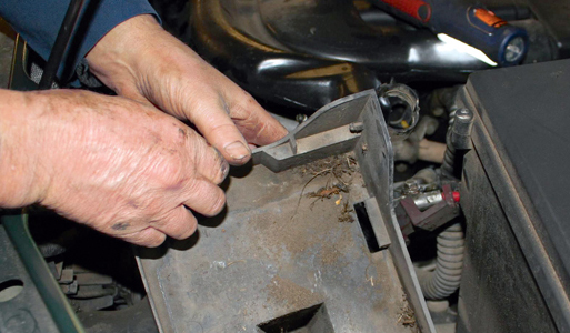
Disconnect the battery terminals, loosen the clamp bolt and lift out the battery. Remove the four bolts securing the battery tray and lift it out (pictured below) making sure you unclip the attached wiring harness.
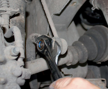
Remove the plenum chamber by undoing the three jubilee clips. Undo the accessible upper bell housing bolts and install the engine support beam. Undo and remove the engine mounting and the two starter motor bolts. Raise the vehicle and remove both front road wheels. Undo and lower the plastic/metal undertray and release the n/s and o/s dust covers. Undo and release the anti-roll bar links (see first picture below) on both sides and do the same with both lower suspension arms. Remove the engine lower steady bar bolts and remove the bar (see second picture below).
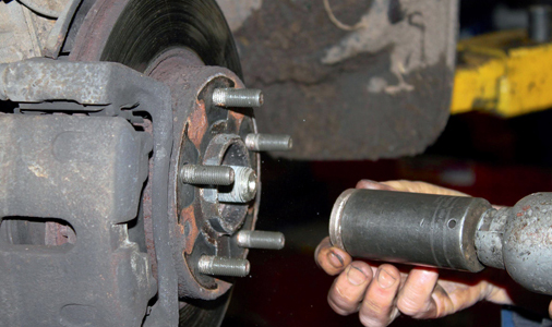
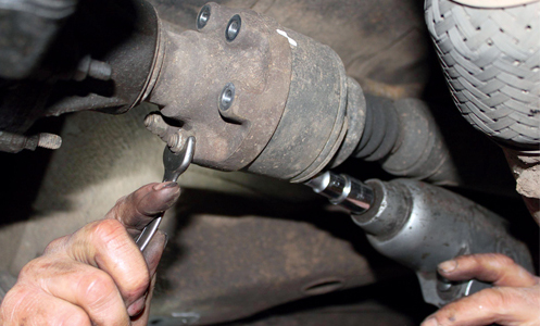
Mark the position of the subframe with a marker then undo and remove both front suspension arm rear joints. With some support release the subframe and lower it to the floor. Drain the transfer box and the gearbox oil then remove both front hub nuts (see first picture below) and release the driveshafts completely. Mark the front propshaft connected to the transfer box and unbolt the propshaft (see second picture below).
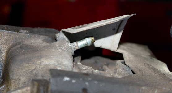
Remove the upper and lower transfer box brackets. Clamp the transfer box coolant pipes and remove them. Undo the four bolts holding the transfer box to the gearbox and release. Lower the transfer box to the floor using a transmission jack, making sure you remove the metal breather pipe beforehand (pictured below).
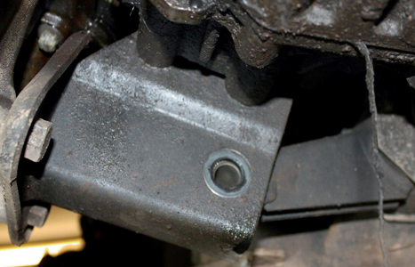
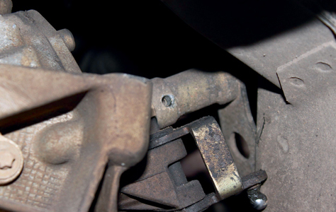
Remove the cover plate bolt at the rear of the gearbox and the bell housing bolts that the transfer box was covering. Undo the two electrical connectors on the gearbox and release the gear selector mechanism. With support, undo the final bell housing bolts and lower the gearbox down slightly. This should give you better access to knock out the gearbox selector dowel (pictured below) and release the selector weights. With the selector weights out of the way you can now lower the gearbox to the floor.
Unbolt the worn clutch, making a note of which way the driven plate is fitted. Check the condition of the flywheel and clean off any debris with a suitable solvent applied to a rag. Make sure the crankshaft rear oil seal and the gearbox first motion shaft seal are in good condition with no leaks. With the clutch removed, check the dual mass flywheel (DMF) for signs of heat stress and evidence of grease loss. The DMF should also be tested for freeplay and rock between the primary and secondary masses (LuK tool number 400 0080 10 is specifically designed for this purpose on all LuK manufactured DMF’s). Full instructions and tolerance data for all LuK DMFs are contained on a CD which comes with this special tool.
The concentric slave cylinder (CSC) should always be replaced when a new clutch is fitted, it is designed to last the life of the clutch not the vehicle. Clean the first motion shaft splines and any debris from the bell housing (especially important when a release bearing has failed). Remember, if the bearing or sleeve is made of plastic there is no need for lubrication. If both parts are metal then a high melting point grease should be used and not copper-based products. Put a small dab of grease on the first motion shaft splines and make sure the new driven plate slides freely back and forth.
This not only spreads the grease evenly but also makes sure you have the correct kit. Wipe any excess grease off the shaft and driven plate hub. Using a universal alignment tool and checking the driven plate is the correct way round (note “Getriebe Seite” is German for “Gearbox Side”) the clutch can be bolted to the flywheel evenly and sequentially.
Before fitting the gearbox make sure the locating dowels are in place and not damaged. Refit any that have become dislodged and refit the gearbox. Make sure the gearbox bell housing bolts are secured before lowering the transmission jack. Rebuild is the reverse of removal, not forgetting to refill the gearbox with oil and quantity specified by the manufacturer.


