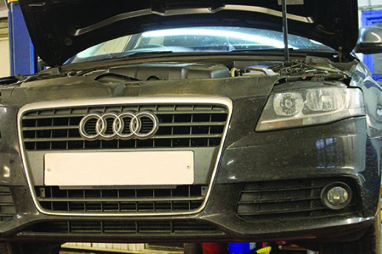
The Audi A4 – with over 300,000 vehicles on UK roads – may sound like a daunting vehicle on which to change a cambelt, but with a little know-how and the appropriate tools, it will prove to be an ideal repair for independent garage technicians. In this particular article, we tackle the A4 2.0 tdi with an engine code of CAGA.
Ensure the engine is cold
The engine on this vehicle has been identified as an interference type, so the likelihood of engine damage, if the cambelt breaks, is very high. It is very important that the belt installation is performed on a cold engine, so plan the job carefully.
Always turn the engine in the normal direction of rotation only – unless advised otherwise by the OEM fitting instructions. Recommended manufacturer’s torque values should always be used, and it is recommended to change the tensioners and the pulleys when replacing the cambelt.
A two-post ramp is ideal for carrying out the replacement, and it is vital that the appropriate timing belt replacement tools are used – these are readily available from most Motor Factors. If the vehicle is equipped with alloy wheels, it is a good idea to locate the adapter key before you start.
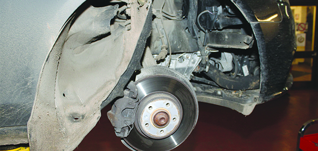
Before carrying out any work, disconnect the battery earth cable. Remove the bumper top closing panel, the cold air intake duct and the engine cover. Disconnect the air temperature sensor from behind the Audi logo attached to the front grille. Raise the vehicle and remove both front wheels. Remove the driveshaft guard and the wheel arch liner fixings – there are quite a lot of fixings to be removed.
In this example, we did not remove the complete liner, but just enough to carefully fold it towards the rear of the wheel arch to allow enough access to the drive system (pictured). Remove the engine undertray.
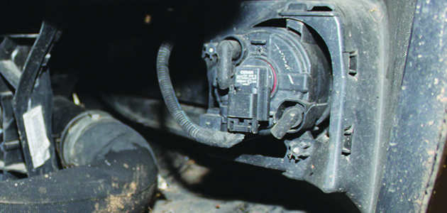
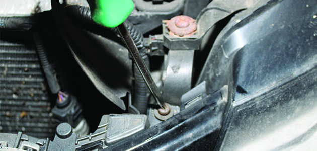
Disconnect the front fog light multi plug connectors on both sides (pictured).
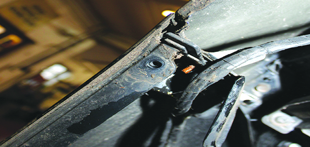
The bumper now has to be removed. This is done by removing the two bolts – one in each wheel arch (pictured)…..
……and the two bolts from the brackets – one on each side next to the headlights (pictured). Disconnect both headlight multi-plugs and the bonnet release sensor wire.
Disconnect the bonnet release cable. Remove the two bolts located on the top of the modular front end (MFE) next to the headlights. Remove the bolts, of which there are three, on each side on the longitudinal member, and replace the top two bolts on each side with either a longer bolt or all thread to slide the MFE into its service position. Disconnect the intercooler pipes and slide the MFE forward into service position. Remove the upper timing belt cover.
Release the auxiliary belt tensioner by turning clockwise and remove auxiliary drive belt. Pop out the crankshaft pulley centre cap and remove the retaining bolts and crankshaft pulley.
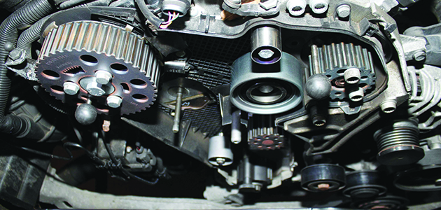
Remove the lower and centre timing belt covers. Rotate the crankshaft clockwise to TDC on No.1 cylinder, ensuring that the TDC markings are in alignment with the camshaft pulley windows positioned at 12 o’clock (pictured), rotate the crankshaft one turn clockwise if not.
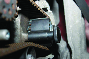
Lock the crankshaft using the special tool and ensure the dowel on the tool is located in the oil seal housing (pictured). Slacken the camshaft and high-pressure pump bolts just enough to allow them to rotate freely on their axis and not tilt. Slacken the tensioner pulley nut and remove the timing belt.
Replace all the tensioner and pulleys and, when installing the new tensioner, it is imperative to locate it in the slot on the belt cover back plate to avoid failure or damage (pictured).
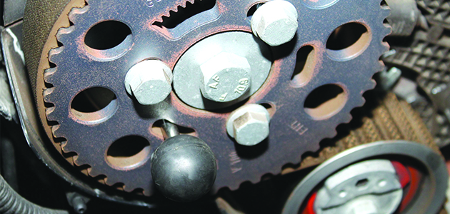
Install the tensioner locking pin (if not already fitted) which ensures the tensioner is in the right starting position. Lock the camshaft and pressure pump sprockets with timing pins (pictured). Turn the camshaft and high-pressure pump sprockets fully clockwise in slotted holes.
Tighten the securing bolts
Remove the locking pin. Rotate the camshaft sprocket anti-clockwise using an anti-rotation tool. Ensure the belt is taut between the camshaft and high-pressure pump sprockets and tighten the securing bolts for the camshaft and high-pressure pump pulleys to a tightening torque of 20Nm.
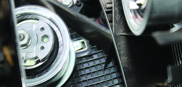
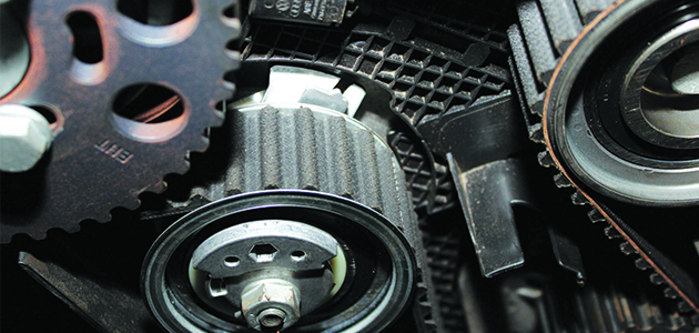
Slowly rotate the tensioner pulley clockwise until the pointer is aligned with the locating notch (pictured). Make sure the tensioner nut does not turn whilst aligning the pointer.
Tighten the tensioner nut to a torque of 20Nm + 45°. Remove the camshaft, high-pressure pump and crankshaft locking tools. Rotate the crankshaft slowly two turns clockwise until just before TDC on No.1 cylinder. Refit the crankshaft locking tool whilst slowly turning crankshaft to TDC and make sure the locating dowel sits inside the oil seal housing. Verify the timing marks are aligned and the camshaft locking tool can be easily inserted.
(NOTE: Do not insert a high-pressure locking tool, as this could be slightly misaligned and does not need adjustment).
Make sure the tensioner pointer is correctly aligned with the locating notch, keeping in mind a 5mm tolerance is permitted to the right of the notch only. Repeat the procedure if this is not the case.
The installation of the remaining parts is the reverse order of removal, but it is strongly advised to check the condition of the auxiliary belt and driven components for excessive wear and consider replacing them. Finally, it is advisable to rotate the engine by hand a number of times before starting the engine to check for any interference or noise.


