In part two of this series, Autel runs through the procedure for Adaptive Cruise Control System (ACC) calibration on equipped VW models, using the MaxiSys ADAS Tablet.
Setting up the vehicle
Set up and perform the calibration frame levelling procedure (this procedure varies slightly by vehicle and system):
1. Park the vehicle on flat and level surface with its front wheels pointing straight. Ensure there are no objects within 3m of the front of the vehicle.
2. Turn the rear axle steering straight.
3. Bring the vehicle to a complete stop, and turn off the ignition.
4. Ensure the vehicle is not carrying any load.
5. Ensure the vehicle’s coolant and engine oil are at the recommended levels and the fuel tank is full.
6. Close all doors and ensure all lights are off.
7. Adjust the tyre pressure to the recommended level.
8. Ensure the battery has sufficient power.
9. For vehicles with air suspension, activate ‘Jack Mode’.
Starting the calibration procedure
10. Attach the VCI to the vehicle and turn on the ignition.
11. Connect the diagnostic tool to the vehicle. 12. Tap ‘Diagnostics’, then the ‘VIN’ button on the upper left of the screen, to identify the vehicle model and the systems that it is equipped with.
13. Select ‘ADAS Calibration’ and perform the ACC calibration.
The following tools are required for the next stage: ADAS calibration frame, reflector, mini reflector, two wheel clamps with laser attachments, hex wrench, tape measure.
14. Place the ADAS calibration frame.
15. Remove the grille on the ACC radar sensor (you may need to refer to the vehicle manual).
16. Note: if not mini reflector is present on the sensor, attach a mini reflector on any flat surface on the radar unit.
17. Move the calibration frame in front of the vehicle. No pattern should be attached to the frame.
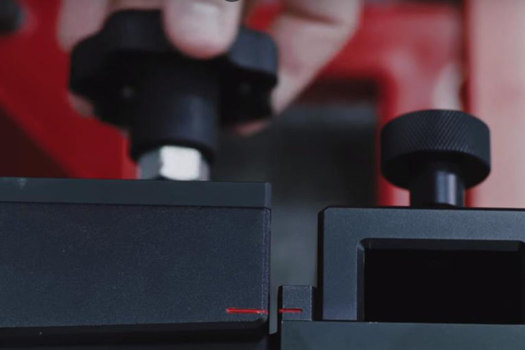
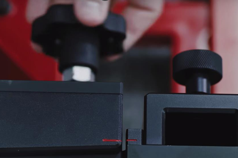
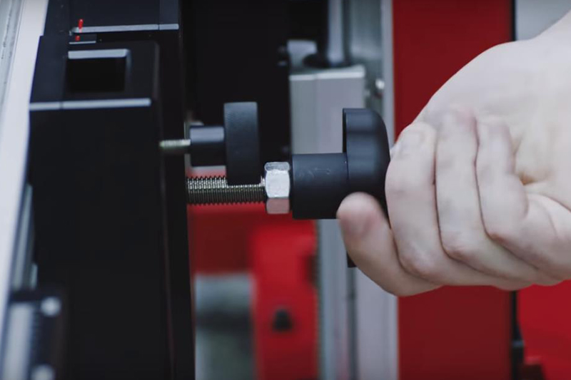
18. Rotate the fine-tuning bolt to align the marked lines (see below)
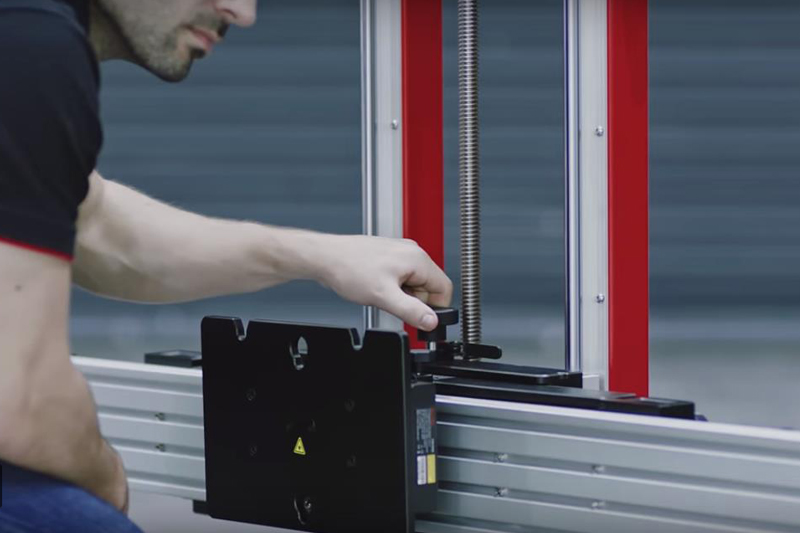
19. Loosen the handle and rotate the fine-tuning bolt until the scale value is zero, and then tighten the handle to secure the crossbar.
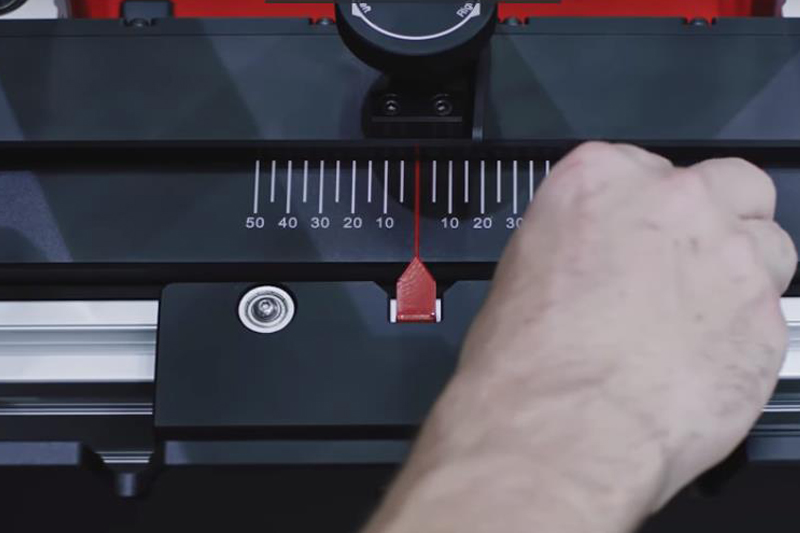
20. Align the pointer on the sliding plate with the zero-marked line, and then tighten the bolt to secure the sliding plate (see below).
21. Turn on the laser, and aim the beam at the front centre of the vehicle.
22. Adjust the height of the crossbar so that it is level with the centre of the front wheel.
23. Move the frame slowly to reach the specific distance between the vehicle and the crossbar sliding plate.
24. When the frame is in position, switch off the laser.
25. Rotate the bolts on the base until they are secured to the ground, but do not overtighten.
26. Attach the wheel clamps to the rear wheels and ensure they are firmly secured.
27. Insert the connecting shaft of the laser into the clamp port. The laser calibration board should be facing the front of the vehicle.
28. Turn on the attached lasers and adjust them so the beams light the rulers on each side of the crossbar cover plate.
29. Loosen the handle and rotate the fine- tuning bolt until the rulers on each side of the crossbar plate have the same value lit by the laser (see below).
30. Tighten the handle to secure the crossbar, and lift the cover plates on each end.
31. Adjust the attached wheel lasers to control the up and down movement of the reflected laser beam. The reflected beam must shine on at least one of the scale boards.
32. Rotate the bolt left or right until the scale values lit by the reflected beam are the same on each side (see below).
33. Now the calibration frame is parallel to the vehicle. Close the cover plates on the crossbar, switch off the lasers on the wheel clamps, and remove the clamps from the wheels.


