Tony O’Donnell, Business Line Manager for UK & Ireland at Chicago Pneumatic, takes PMM through how to correctly set up an air line system in a garage environment.
A garage with a well set-up air line system for its compressed air tools will run a lot smoother, as the tools used will perform to specification and reduce downtime on tool repairs. Let’s face it, technicians are busy enough servicing/repairing cars.
When it comes to compressed air pressure, higher isn’t always better. A good starting point is to check that you have the correct sized air line hose. Additionally, if it’s retractable and is wall/fixture mounted, this is ideal for garages as the hose does not become a trip hazard.
Following this, make sure you inspect the FRL (filter regulator lubricator). Check the tool’s airflow requirements in the manufacturer’s guide to ensure that the FRL chosen is greater than the tool’s requirements.
What does the FRL do?
The filter separates impurities that often appear in older air line installations, such as rust particles and water. Chicago Pneumatic claims that its filters can separate up to 98% of water when operating within its range, and have an especially low pressure drop.
The regulator ensures that the pre-set working pressure remains constant regardless of pressure variations in the intake air or minor variations in the airflow rate. For example, if the pressure is 1bar higher than is necessary, there is a 16% increase in air consumption.
The lubricator supplies the air hose with air line oil in an oil mist, which lubricates the tool in a controlled way, prolonging its operating life and ensuring its efficiency in use.
It is also recommended that one FRL unit is used per tool, and that an air fuse is fitted directly after the FRL. This will shut off the air flow with immediate effect in the event of a hose being damaged. Without a fuse, a hose that is being charged with compressed air could present a serious hose whip hazard within the work area.
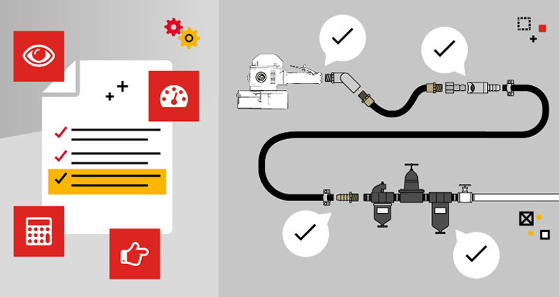
CHICAGO PNEUMATIC’S THREE STEPS TO AIR LINE SET-UP
- Calculate whether there is a pressure drop between the FRL and the tool inlet by reading the FRL gauge value and measuring the dynamic pressure at the tool’s inlet. If a difference is shown, there’s a pressure drop, and this is most often found between the pipe and the end of the tool
- Identify where pressure is being lost by checking that your accessories have been selected and installed properly. There are various points to inspect, especially at the tool’s inlet, the couplings/nipples, the hose connections, and the FRL. In order to avoid pressure drops, make sure that accessories have the correct diameters and thread sizes/types, that the hose used is not longer than required, and that hose clamps are correctly tightened
- Final measurements and adjustments. Once you are confident that all accessories have been selected and installed correctly, measure the dynamic pressure at the tool’s inlet again. Adjust the FRL regulator accordingly to ensure that there’s a reading of 90psi/6.3bars at the tool’s inlet.