
SYMPTOMS
■ Lack of communication with all control units, except the ECU.
■ Tachometer is not working.
■ Instrument cluster not illuminated.
■ Missing communication (with all control units) faults in the only control unit that was communicating.
ANALYSIS
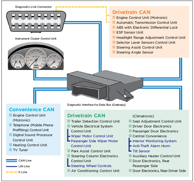
■ Communication with all control units (except the ECU) is effected via the CAN ‘gateway’.
■ The ECU is connected to the CAN gateway, but also directly connected to the on-board diagnostic link connector.
■ The immobiliser control unit is located in the instrument cluster. In the event of no communication with the instrument cluster (as proved by the fault codes stored in the ECU) it should be impossible to start the car. The vehicle is running, however.
Communication is a critical aspect relating to the construction of modern cars. It has a dual function:
1. The communication between individual control units in a vehicle. An example of this is that the ECU transmits engine speed information to the automatic transmission control unit. This enables the automatic transmission control unit to make a decision about whether to shift gears or remain in the current gear.
2. The exchange of data between on-board control units and the diagnostic tester.
Vehicle details
In this article we’ll cover both communication examples and show their mutual correlation, using the 2008 Volkswagen Caddy as an example.
The on-board communication in this vehicle – both the communication between the control units and the communication used for diagnosis – runs via a digital CAN bus.
The on-board control units aren’t provided with autonomous diagnosis, which means that they communicate with the diagnostic tester using a dedicated control unit, called a CAN ‘gateway’.
The only exception is the ECU. This is connected to the CAN gateway but, at the same time, it is also directly connected to the on-board diagnostic link connector and will use diagnosis that is independent from the CAN gateway. A schematic diagram of control unit connections to the CAN gateway can be seen in the diagram below.
Fault description
The vehicle in for repair was suffering with an electrical fault. Traces of previous activity (likely undertaken by other car mechanics) was clearly recognisable as the control units installed had marker pen inscriptions on them and the ECU itself showed traces of being opened.
Once the tester was connected, it turned out that the only control unit able to communicate was the ECU. The fault codes stored in the ECU indicated a lack of communication with other control units including, among others, the instrument cluster.
So, in the case of a ‘non-communication’ with the instrument cluster and the fault in communication with the ECU, one could legitimately ask the question of why the engine could be started at all, since the non-communicating instrument cluster also acts as the immobiliser. The analysis of the engine’s EEPROM showed that the immobiliser had, in fact, been deactivated.
After reviewing all of the information and symptoms we had available it was then a case of trying to analyse the data and determine the next step.
Course of action
1. We connected the CDIF/3 tester from AXES and selected VW Caddy (2K) from the list.
2. In the top menu we then selected “Scan” and began the scanning procedure. The only control unit displayed on the list of scanned control units is the engine. Based on the analysis of the schematic diagram illustrating the connections of control units we know that the communication between all control units runs via the CAN gateway. The ECU, which maintains the communication, is connected to the CAN gateway (similar to other control units) but at the same time is also directly connected to the vehicle’s diagnostic link connector.
3. We then checked the fuses installed in the vehicle. All fuses proved to be OK.
4. The key component for the communication of systems in the vehicle is the CAN gateway, so this was removed from the vehicle and connected to the tester directly on the table in order to verify its correct function outside of the vehicle electrical system. It turned out that the gateway control unit was communicating OK. Once the CAN gateway control unit was verified, our focus was shifted to the vehicle electrical system. The pin assignment of the control unit was as follows:
+12V 1, 2, 14
GND 11, 12
CAN High 19
CAN Low 9
5. We then checked the power supply on pins 1, 2 and 14 against the ground – there was no power supply on any of those three pins. Since the feed lines run to the fuse box near the battery in the engine compartment, we inspected the fuse box and found a burnt path inside.
6. In order to confirm that the fault we had found was having an immediate impact on the malfunction of our car, we decided to conduct an instant repair by soldering a wire in the missing path area.
7. After the ignition was switched on and the tester connected all control units were scanned again. This time the communication had been established with all control units. Switching the ignition saw the instrument cluster illuminate and the tachometer worked again once the engine was started.
8. We ordered a new fuse box and, after its replacement, the vehicle was once again fully operational.
Conclusion
This wasn’t an obvious case as the vehicle was starting thanks to the deactivated immobiliser. Additional symptoms, such as no illumination of the instrument cluster and the defective tachometer, made the entire picture seem less logical than it should have done at first.


