
Despite what the experts say, oxygen sensor diagnosis isn’t easy. When an oxygen sensor fails completely, the effect it has on the system throws up enough information to make the culprit stand out like an elephant in a polar bears-only golf club!
It’s when the sensor is ‘on its way out’ that complicated problems arise. The DTCs and data that we see can be very difficult to interpret, and often the sensor is changed to eliminate potentially incorrect information from a ‘dodgy’ component; however, we all know this isn’t best practice and it’s an injustice to pass on the cost of a sensor when its replacement has no effect on the problem.
Recently, a technician found himself in a situation where he replaced the front oxygen sensor on a 2009 Toyota RAV 4 with a running fault. This decision was based on the strength of a P0171 fault code and a quick test with a voltmeter, which gave ‘odd’ readings.
The sensor cost nearly £200 and had made no difference to the poor performance. The odd reading of 0.3V was taken across the sensor wires and never changed – whether the engine was running or not. The new sensor gave the same reading, so he contacted Blue Print for some help and advice.
The problem is that the sensor has four wires – just like most others – but it’s actually a Wide Band Oxygen Sensor or Air Fuel Ratio (AFR) Sensor. These types of sensor have been in use for many years and are very reliable, which is just as well, because their diagnosis is a far cry from that of a conventional O2 sensor.
How does it work?
Well, what it doesn’t do is produce a voltage signal that flicks between 0.2V and 0.8V in response to the ECM (Engine Control Module) adding and removing fuel from Lambda 1; instead it shows a steady 0.3V no matter what.
What is going on?
The sensor is similar to the conventional Zirconia narrow band in that it uses the same material, but is planer in construction; it’s the way it’s used that makes the difference. Narrow band sensors are described as ‘passive’ because they produce their own voltage from the different O2 levels on the platinum electrodes, which are exposed to oxygen from the air and exhaust. AFR sensors are driven by some clever electronics in the ECM – Fig 1 (below) shows a simplified control circuit.
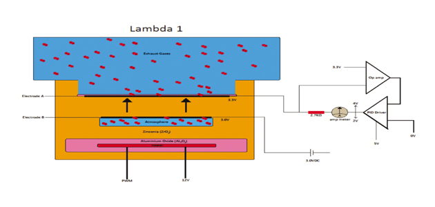
(Fig1)
The PID, (Proportional Integral Derivative) Driver is a clever device that can compensate for a deviation from a set point, proportionally and very quickly.
On Toyotas, when the engine is running, at Lambda 1 the sensor produces a voltage of 0.3V measured across the sensor. The Electrode B exposed to the atmosphere (air reference chamber – normally negative) is supplied with 3V from the ECM; Electrode A consequently has a voltage of 3.3V (3V +0.3V). The job of the PID Driver in the ECM is to maintain the 0.3V difference no matter what the oxygen level in the exhaust.
At stoichiometric (Lambda 1), the voltage at Electrode A is 3.3V and is connected to the Op amp; the other input to the Op amp is a fixed 3.3V. The Op amp outputs the difference in voltage between the two inputs. The job of the PID Driver is to maintain the voltage of Electrode A at 3.3V. So, at Lambda 1, the voltage output of the Op amp is 0 and, consequently, the PID Driver outputs 3.3V to balance the voltage at Electrode A and no current flows across the resistor.
When the engine is running weak the voltage at Electrode A drops. The Op amp then outputs a positive voltage and the PID Driver reacts by increasing the output voltage supplying Electrode A, which raises it back to 3.3V and results in a current flow across the resistor. The weaker the mixture, the greater the PID Driver’s output voltage, which, therefore, increases the current flow across the resistor.
When the engine runs rich the opposite happens, the voltage at Electrode A increases and the Op amp outputs a negative voltage. The PID Driver, in turn, lowers its output voltage, causing current to flow from Electrode A to drain through the PID Driver and maintaining the 3.3V at Electrode A.
The PID Driver’s output voltage and current flow indicate how rich or weak the engine is running. Something to bear in mind about the differences between AFR sensors and conventional O2 sensors is that the voltage signal indicated on the scan tool goes up – not down – when the fuel mixture is weak.
Also, because the voltage signal is coming from the PCM and not the sensor itself, you can’t use an oscilloscope to see the sensor’s reaction to changes in air fuel ratio, like you can with a conventional O2 sensor.
Why do we use them?
AFR sensors indicate how rich or weak the mixture is, so that compensation can take place quickly. Narrow band sensors only indicate ‘rich’ or ‘weak’, so compensation for a very weak or rich mixture can take a long time, causing emissions and driveability problems. Narrow band sensors don’t work with diesels or GDI (Charge Stratified Mode); AFR sensors do.
Testing the sensor
Nissan, Toyota, Mazda and some other Asian manufacturers have active test software built into their PCM that allows the technician to alter the fuel injection quantity, in order to produce rich and weak mixtures. Normal mixture compensation is switched off during the active test and the system reverts to normal fueling when the test is cancelled.
Note: Engine coolant temperature must be above 80˚C.
Using injection quantity
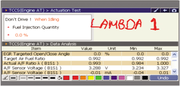
At Lamba 1, sensor voltage is close 3.3V and no current flows.
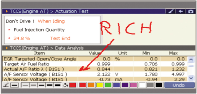
As fuel is added, the ECM responds by lowering the voltage to the sensor and the current drains away.
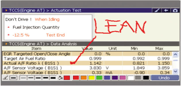
As fuel is reduced, the ECm responds by raising the voltage to the sensor and current then flows to it.
The diagnostic tool used to carry out the Actuation Test is Blue Print’s G-Scan. The G-Scan allows you to carry out the test on the fuel injection system, whilst viewing the resultant changes in voltage provided to the sensor.
If your scan tool doesn’t have this function, the sensor can be tested in the following way:
1. Make sure the engine coolant temperature is over 80˚C.
2. Hold the engine speed at around 2,500rpm.
3. The sensor should read approximately 3.3V / 0mA (respectively) at Lambda 1.
4. Now accelerate to 4,500rpm and quickly release the throttle, allowing the engine to return to idle – this should weaken the mixture as the fuel shuts off on overrun.
5. You should see the voltage momentarily rise to 3.8V – 4.0V, indicating the sensor has recognised the weak mixture.
In conclusion…
- It’s more likely that the fault isn’t caused by a faulty sensor, so check all the usual suspects.
- Check the Long Term Fuel Trim (LTFT) – figures of 8-10% or more should be investigated.
- High LTFT values mean fuel is being added to compensate for a weak mixture, so look for air leaks. A small air leak will weaken the mixture more at idle than at higher engine speeds because the leaked air becomes a smaller part of the total air intake.
- Look for the Short Term Fuel Trim (STFT) starting to contradict LTFT as the engine speed increases.
- Check for exhaust leaks, which can allow air to enter the exhaust.
- Check the coolant and air temperature sensors for plausible readings.
- Check that the MAF sensor is responding correctly.
- Check that the fuel pressure is within specification.


