
The effects of turbocharger faults differ slightly from petrol to diesel. The theme of this article deals predominently with diesel, which is by far the most common application.
Please note: the following procedures and data are generic and should not be used instead of manufacturer’s procedures and data.
Turbocharger problems fall into two distinct categories: the turbocharger and the turbocharger control system. Other lack of performance issues, which point to the turbocharger, may distract the technician from the true source of the problem. With this in mind diagnosis is best done when all the information is considered.
A modern turbocharger should last as long as the engine itself and, other than inspection of pipes and hoses, doesn’t require any special maintenance. What is essential is that correct service schedules are met and the correct lubricants are used.
Mechanical problems
It is worth noting that most mechanical issues can be diagnosed without serious dismantling or removal, although access to turbochargers fitted to the rear of the engine can often hinder inspection. Mechanical problems may be accompanied by noisy operation.
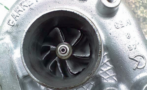
Firstly, look at the inlet compressor by removing the inlet pipe. Spin the shaft and feel for excessive shake or roughness. Hold the centre of the shaft and move it up and down to check for radial wear and push and pull for axial end float – some play is normal. This is the oil clearance that allows the shaft to float on a film of oil.
Typical values are:
■ Radial clearance – 0.07mm-0.15mm (0.003in-0.006in)
■ Axial clearance – 0.02mm-0.06mm (0.001in-0.003in)
Excessive free play can cause the compressor or turbine to scrape against the casing, so feel for resistance as you turn the shaft whilst pushing and pulling the shaft. Inspect the blades of the compressor, looking for cracks and nicks which may throw the assembly out of balance. Look for oily deposits which may indicate shaft seal problems. If the turbo is difficult to see, try using an illuminating webcam or one of the proprietary inspection scopes.
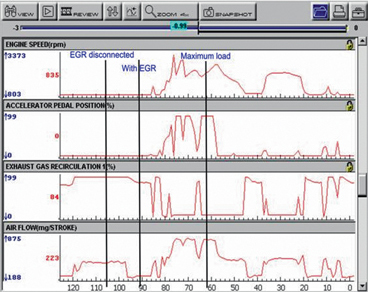
Checking turbo boost pressure
This is best done using a vacuum/pressure gauge but can be monitored on your scan tool. If boost pressure is low, check the air flow corresponds. If the air flow is higher than boost pressure indicates, then suspect a leak in the induction tract. Inspect the intercooler pipes and induction manifold. A smoke machine leak tester is a very useful tool for this sort of problem. If both airflow and boost pressure are low, check for a blocked exhaust.
A quick calculation for airflow in kg/hr is:
■ Engine capacity x RPMx 60 x MAP2000
■ Where MAP is measured in bar absolute i.e. 700mb = 0.7bar
■ This calculation assumes the EGR is disconnected.
Turbocharger wastegate
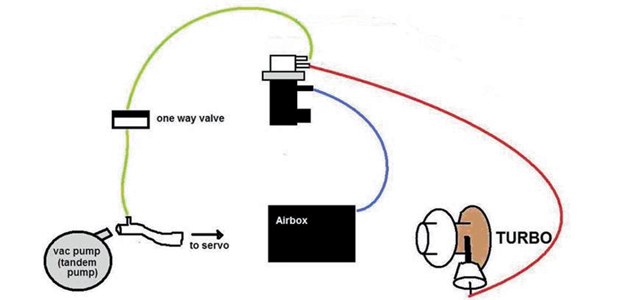
Try to observe the operation of the wastegate – connect a vacuum pump and gauge to the waste gate actuator and operate the wastegate. making sure that it opens and closes without sticking. Look at the gauge and check there is no pressure drop. At this point you will need to familiarise yourself with the operation of the wastegate. Some wastegates default to the open position and some to the closed. This means that those with a normally open default need to have a vacuum applied to close the wastegate. This is done to avoid over-boost problems should the vacuum system fail. Conversely the normally closed wastegate will only have a vacuum applied if boost pressure is to be regulated.
Checking a normally open wastegate
Check a normally open wastegate with the vacuum gauge T’d in between the VSV and wastegate actuator. With the engine running you should read around 15 in hg. Now disconnect the electrical connector – the vacuum should disappear.
Checking a normally closed wastegate
A more conclusive check for a normally closed wastegate is to connect the vacuum gauge into the pipe between the vacuum solenoid valve (VSV) and the actuator using a T piece. Disconnect the electrical connection on the VSV. Apply a vacuum and watch the operation of the wastegate. Check that the vacuum is held and there are no leaks in the VSV, pipe work or actuator diaphragm. Now refit the electrical connection and using your scanner’s ‘active test’ function, operate the wastegate – the vacuum should disappear.
Check that there is no vacuum when the engine is running. Any indication of VSV failure should be followed up by an electrical check. The VSV valve is operated by a pulse width modulated signal so check the integrity of the signal using an oscilloscope. If the signal is good, check the resistance of the solenoid windings (usually around 12 ohms).
Checking the vacuum pump
Vacuum pump failure will normally be accompanied by a hard brake pedal, but in systems with power brakes there will be little indication of any problems. Start by T’ing the gauge into the pipe between the engine’s vacuum pump and the VSV. Start the engine and check the vacuum – it should produce around 20-25 in hg.
Turbocharger over-boost
Over-boost problems are usually associated with wastegate issues. They are generally caused by stuck wastegate valves or faulty boost pressure control systems. Getting the wastegate to open can require boost pressures of around 2 bar and this can often only be achieved on a road test or on a dynamometer. To observe the boost pressure you will need to use your scan tool in ‘graphing’ mode so you can analyse the data safely or have an accomplice. On engines which do not have a MAP or boost pressure sensor, you will need a boost pressure gauge on a long pipe carefully routed through to the engine bay. Maximum boost pressure should never exceed manufacturer’s data.
Over-boost problems associated with variable geometry turbochargers
The VGT does not normally have a wastegate, but instead can vary the angle of nozzle vanes to control boost. A common problem is carbon build up around the nozzle vanes. This is usual in vehicles which are used for short journeys or engines that are producing excessive black smoke for whatever reason. When this happens the actuator struggles to move the vanes in response to command; this normally causes temporary increases in turbo boost pressure.
To protect the engine from damage, the boost pressure is monitored and, should excessive boost pressure be detected, the turbo vanes are commanded to the steep position and the turbo boost is lost. Depending on the strategy of the management system it may also put the engine into ‘limp home’ mode. This causes dramatic power loss.
It is normally reset with the ignition and an ‘excessive boost pressure’ DTC is set. The repair of this unit is not as difficult as it may seem and is certainly cheaper than buying a replacement. Some companies are offering a chemical decarbonising process but at present we have no information of how effective it is. As always, the underlying cause of the carbon build-up should be investigated.


