Dayco provides step-by-step guides for replacing the timing belt kit on two vehicles: the Alfa Romeo Mito and the VW Golf Mk VII.
This step-by-step technical guide will help technicians through the process, helping to avoid complications and ensuring a first-rate job. As with all primary drive system jobs, the work should be undertaken when the engine is cold, so ideally the vehicle will not have been run for at least four hours.
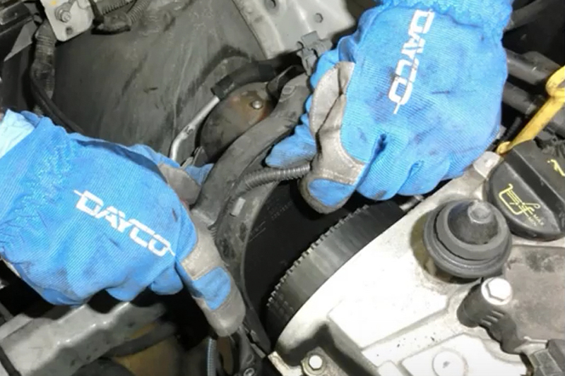
Remove the cowling from under the engine and the driver’s side front wheel arch to expose the auxiliary belt system. Slacken the auxiliary belt tensioner with a spanner and take off the belt, and then remove the crankshaft pulley. This will reveal two electrical connectors, which need to be disconnected, followed by the tensioner.
Take off the upper engine case, loosen the fasteners on the air filter hoses and then remove the complete air filter housing to access the timing case cover. Undo the screws of the timing case and, while taking care to detach the wiring connected to the upper half (see below), remove both parts of the timing case.

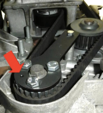
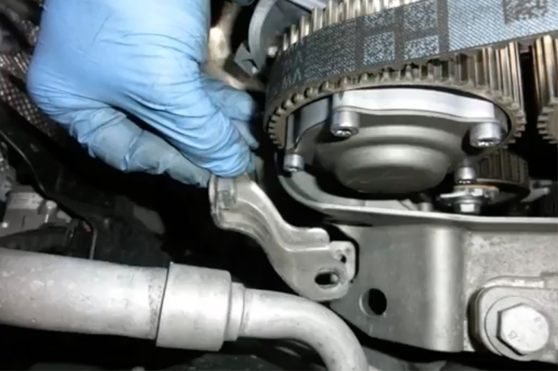
At the opposite end of the head, remove the oil vapour collection housing, followed by the vacuum pump mounting bracket and then the pump itself, to allow the installation of the camshaft timing tool (2000034400). Returning to the timing drive end, install the crankshaft timing tool (2000004500), ensuring that the pin in the pulley is located correctly (see below).
After suitably supporting the engine from underneath, remove the upper engine mount and bracket to reveal the entire timing drive system. Loosen the tensioner bolt and then remove the tensioner and belt, followed by the water pump.
Ensuring that the cooling system has been flushed through and no debris is present, install the new water pump from Dayco kit KTBWP2853, complete with its seal.
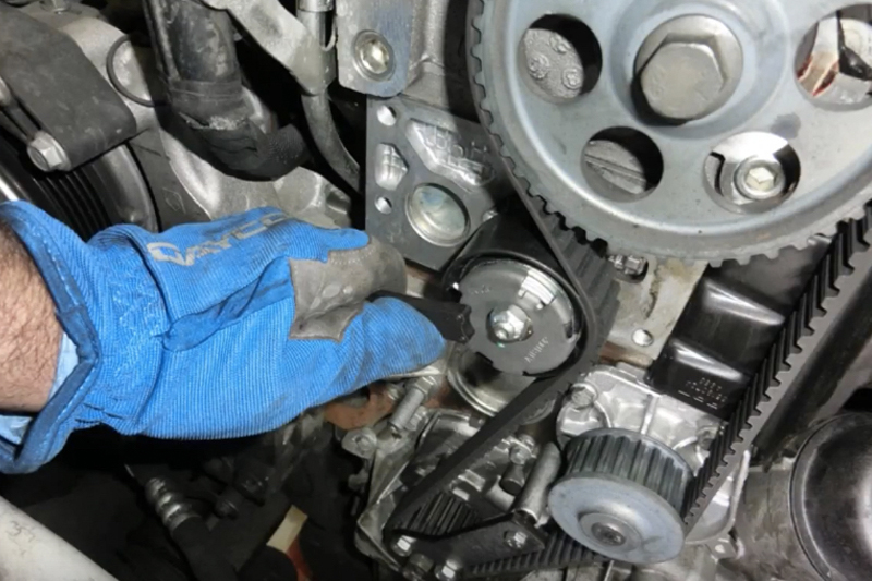
Hold the camshaft pulley and loosen – but don’t remove – its bolt, so the pulley can rotate on the shaft. Replace the tensioner and the belt with the new ones from the kit and, using tool (1860987000), rotate the tensioner anti-clockwise to the end of its stroke (see below) and tighten the nut to 27Nm. Making sure the camshaft pulley doesn’t move by holding it with a suitable tool, tighten the bolt to 132Nm.
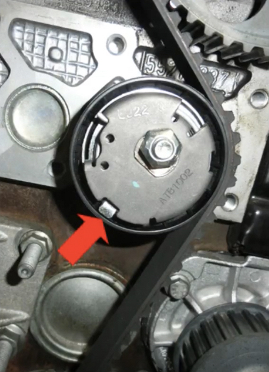
Remove the camshaft and crankshaft timing tools and by using the crankshaft pinion, rotate the engine several times and reinstall the tools. Then, while holding the tensioner with the tool, loosen the fastener and rotate the tensioner until its index is centred in the reference window (see below), then retighten the fastening to 27Nm. Remove the timing tools and refit all the components in their reverse order, and if necessary, replace the alternator pulley with Dayco ALP2440, crankshaft pulley with Dayco DPV1028 (the fasteners for which should be tightened to 28Nm) and the auxiliary belt tensioner with Dayco APV1079. However, Dayco recommends the auxiliary belt 5PK1150S is always replaced.
VW Golf MkVII – 1.4L TSI petrol engine; Dayco Kit KTB819
Start by removing the plastic guard from underneath the engine and then, after taking off the front offside wheel, the lower part of the plastic cowling from inside the wheel arch. This will reveal the auxiliary belt system, and by relaxing the tension on the belt with a spanner on the tensioner, the belt can be removed. Before disconnecting the tensioner, lock it by inserting a pin as shown (see below).
Remove the cap in the engine block used to close the hole in which the crankshaft timing tool will be inserted and then disconnect the air intake to the filter box. Then take out the filter box and detach the pipes between the throttle and turbo, and the filter box and turbo, as well as the oil vapour recirculation pipe and the turbo air intake connector.
Now remove the water pump belt cover and the cover on the gearbox side of the intake camshaft, drain the cooling system and take off the upper cover of the water pump and the expansion tank, as the water pump and water pump belt should be changed at the same time.
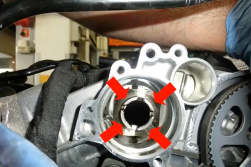
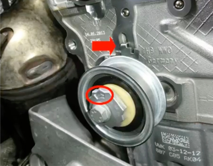
Detach the upper timing belt cover, which will expose the two variable valve timing units – the exhaust camshaft on the left, the intake on the right – and rotate the central crankshaft pulley screw clockwise and position the intake camshaft as viewed from the gearbox side as shown (see below).
Insert the crankshaft timing tool (T10340) and fully screw into place, before rotating the crankshaft until the shaft rests on the tool. Then fit the camshaft tool (T10494), and, after making sure it is in the correct position, lock it with a screw.
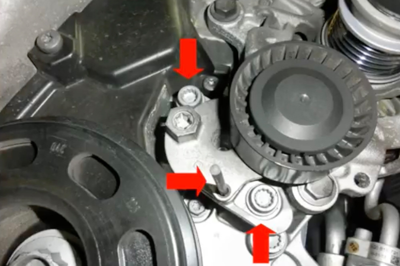
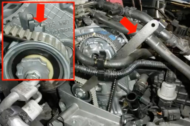
Remove the crankshaft pulley, followed by the lower timing belt cover and the two alternator retaining screws to detach it. Then take off the plate shown (see below), support the engine appropriately from above, and, remove the top engine mount adjacent to the timing belt and take off the central timing belt cover to access the tensioner and idler. After removing the cover of the left (exhaust) and the central cap of the right (intake) variable valve timing units, take off the tensioner and timing belt. Appropriately lock the valve timing units, and then remove the centre screws and the units themselves.
Attach the new idler, Dayco ATB2637, and torque to 45Nm, then the tensioner, Dayco ATB2636, ensuring it is fitted as shown (see below), and then fit the valve timing units on the corresponding camshafts, but do not fully tighten their screws.
Fit the new timing belt, Dayco 941060 and, always rotating it (the belt) clockwise, use tool, T10499, to move the needle of the tensioner to the right about 10mm beyond the fixed reference and then back to the middle as shown (see below), and tighten the tensioner fixing screw to 25Nm.
Suitably lock the valve timing units and tighten their screws to 50Nm before removing the camshaft timing tools and temporarily refitting the crankshaft pully to enable the engine to be turned through a few clockwise revolutions.
Check the belt tensioner needle remains in the right position, and using the crankshaft and camshaft tools, the timing is still correct. If so, appropriately lock the valve timing units and tighten their screws another 135°. Now remove the water pump with the belt drive and, after flushing out the cooling system to remove any debris and cleaning the water pump facing, reposition the replacement pump, with the new belt, Dayco 941094, at the same time.
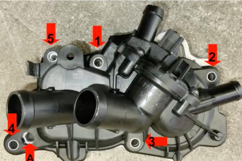
It is extremely important to follow the correct tightening procedure when reattaching the water pump cover, so first tighten the screws to 10Nm in the sequence shown (see below) and then loosen by one turn. Put a hex screw in ‘A’, torque to 30Nm and hold the torque wrench in position while retightening screws 2, 1 and 5 to 10Nm and then 3, 4, 5, 1 and 2 to 12Nm.
Refit the components in reverse order of their removal, tension the crankshaft pulley screw to 150Nm + 180° and the crankshaft timing tool cap to 30Nm. To follow best practice, Dayco also recommends the replacement of the auxiliary tensioner Dayco APV3270 and the auxiliary belt Dayco 6PK1000. Finally, refill the cooling system, start the engine and carefully check for leaks and ensure the radiator fan is operating correctly. Then, once the engine is cold, check the level of the fluid again.


