In the first part of this feature, PICO Technician Steve Smith investigates a 2005 Vauxhall Vectra, the engine of which is (mostly) refusing to start.
Vehicle information
Manufacturer: Vauxhall
Model: Vectra Auto
Year: 2005
Transmission: Automatic
Mileage: 90,979 miles
Failed part: Engine ECU and Starter motor
Customer’s description
The customer reported a clicking noise from under the bonnet when attempting to start the engine (the engine failed to crank).
Technical description
Verifying the customer complaint is an essential step in the diagnostic process but is also quite often a time-consuming task with no success. On this occasion, the customer’s complaint was verified. The engine failed to crank and there was a clicking noise from the starter motor when we held the ignition key in the crank position. The warning lights in the instrument panel would also flicker in unison with the clicking from the starter motor. When we applied a boost pack to the vehicle battery, the engine would occasionally crank and start as normal, accompanied by a screeching noise from the starter motor.
In contradiction to the above, there were several occasions where the engine would crank and start as normal without support from a battery boost pack (i.e. there was no apparent fault).
Diagnosis
With the customer’s complaint verified, we confirmed the Vehicle’s ID and Specification.
Confirmation of specification is of the utmost importance when it comes to diagnosis. Owners often get tempted to modify their vehicle with fashionable accessories that lack the fundamental quality control and engineering that was intended for the vehicle. The customer confirmed that no such accessories had been installed.
The Customer Interview follows the four “targeted” open question principle below, to help establish facts from fiction:
How long has the problem been evident?
No previous experience of a non-crank/start event or any engine running problems
When did you first notice the problem?
The symptom occurred when attempting to start the vehicle after it had been standing for over six months (MOT was due).
Has any work been carried out on the vehicle recently?
No work had been carried out before the non crank event.
When do you experience the problem?
When attempting to start the vehicle, once started the engine would continue to run.
Quite often, the customer interview leads to a “probable” diagnosis. My initial thoughts turned to low battery voltage (parasitic drain) or 12 V battery failure since the vehicle has been stationary for several months and applying a booster improves the non-cranking issue.
A basic inspection confirmed no fluid leakages, no visible signs of damage to hoses, connections or wiring harnesses, and no sign of accident repair.
A vehicle scan of all on-board control units revealed several fault codes which were saved then erased:
Steering
C1550 Control unit Malfunction
U2105 Communication with engine control unit – Communication faulty
Brake control unit
U2105 Communication with engine control unit – Communication faulty
Steering column switch module
U2105 Communication with engine control unit – Communication faulty
Instrument cluster
U2105 Communication with engine control unit – No communication
Before diving in, we took a step back and checked for Technical Bulletins. This check is paramount. While this may seem obvious, there are many avenues you can take to obtain free technical bulletins and so-called “known fixes”. I have learned that while the entire description of such obtained data matches the exact symptom you are experiencing, the information obtained may well be for other markets i.e., not applicable to UK specification vehicles. (Please don’t fall into this trap as I have with previous vehicles.)
Possible causes
- Battery and charging system (inc. parasitic drain)
- Cranking control circuit
- Starter motor assembly (Screeching noise upon cranking)
- CAN network communication error
- Engine management system input error
The action plan
The action plan was predominately governed by accessibility, probability and cost. We quickly eliminated the battery and charging system as we confirmed them to be OK.
Based on the acquired scan data, you can’t ignore numerous ECUs reporting loss of communication with the Engine ECU. Again, it was tempting to dive into CAN network diagnosis but I felt as though we could be working blind. To understand how such CAN errors could influence cranking, we needed to interpret how the starter motor was controlled and this was where we focused our attention, referring to the relevant technical information.
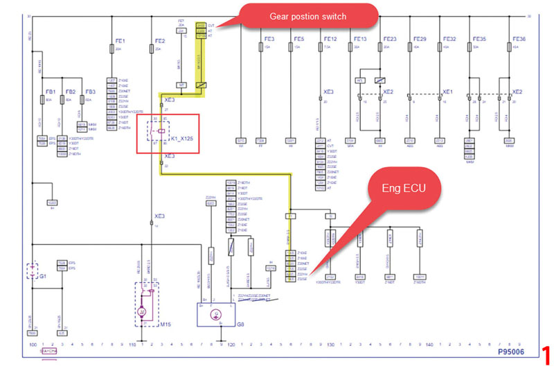
The cranking circuit relied on the engine ECU to ground pin 85 of the starter motor relay, the diagram from ALLDATA (Fig.1/main image) helped clarify the circuit. This diagram shows:
- The ignition switch supplies the gear position switch with a 12 V supply when held in the cranking position
- If the gear position switch is in either Park or Neutral position, the supply from the ignition switch is allowed to pass onto pin 86 of the starter motor relay
- The starter relay (pin 85) is then grounded via the engine ECU (closing the relay contacts) and cranking can commence
So, what was causing the starter motor to repeatedly “click” and the engine failing to crank? The Autodata wiring diagram (Fig.2) will assist with the descriptions included in the waveforms, where we caught the failure.
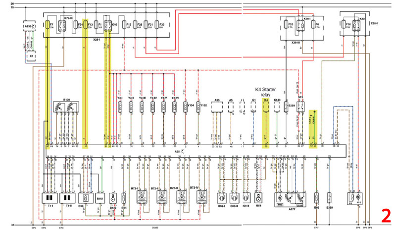
Fig.3 shows how we captured the engine ECU failing to keep starter relay pin 85 grounded, and pulsing the ground path instead (see Channel E).
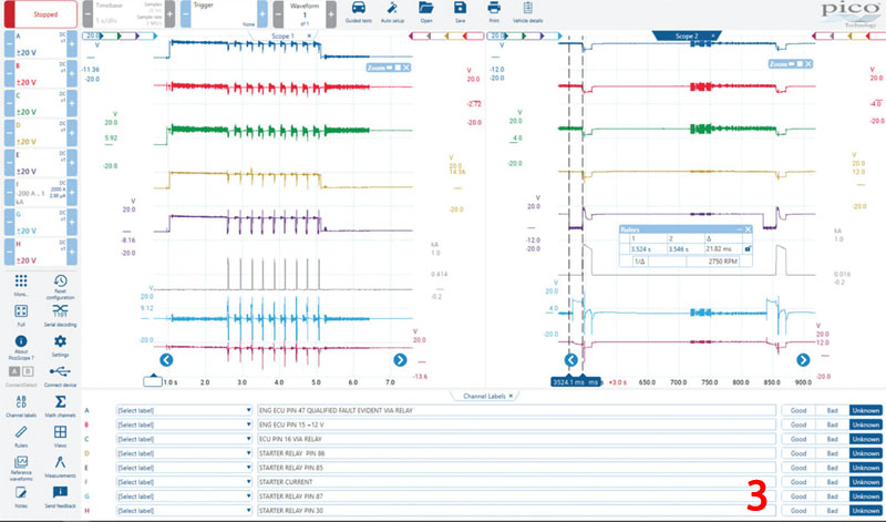
The result, therefore, is the rapid energising and de-energising of the starter relay and, of course, the engaging/disengaging of the starter motor as a direct consequence.
Since we had eight channels to acquire data with, we could eliminate numerous components in one single capture. In Fig.4 we have zoomed in on just one of the “pulsing” events of the starter motor relay.
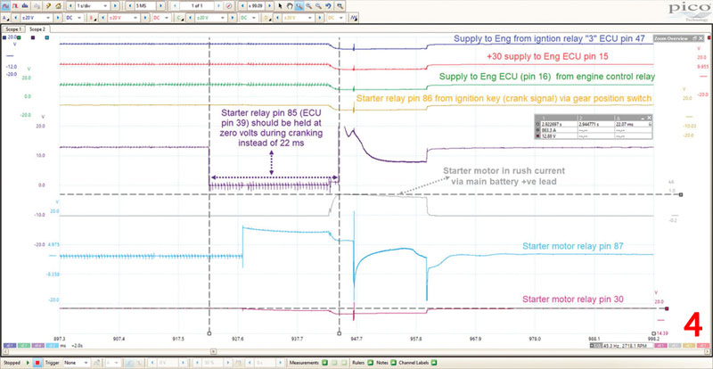
When we referred to the captures and wiring diagrams we could conclude the following:
- The engine ECU did not lose any of the three power supplies to pins 15, 16, and 47 during intermittent cranking, our ignition/engine control relays and circuits were, therefore, OK
- That also meant that the fuse boxes and the terminals “housing” the above relays had to be OK
- The signal from the ignition key to the starter relay pin 86, via the gear position switch, was OK
- The power supply to starter relay pin 30 was OK
- The starter relay was OK, as it was simply responding to the pulsed ground of Pin 85
- The starter motor did momentarily energise based on the inrush current captured on Channel F
All in all, a set of worthy test results that allowed our focus to firmly shift to the engine ECU and our numerous CAN codes reporting a loss of communication (we are not working blind). It is always comforting to know the diagnostic path you have chosen is the right one and by this, I mean validation of the test results shown. We knew the starter relay was losing the ground path on terminal 85 and what better way to qualify this scenario than using a bypass test?
With the ignition on, we removed the starter motor relay and joined terminals 30 to 87 in the engine bay fuse box. The vehicle cranked and started every time (accompanied by a screech from the starter motor). This test qualified, beyond any doubt, that we were justified in pursuing the ground path of the starter motor relay via the engine ECU.
While we have tested the ECU power supplies, what about the main ECU grounding?
Given that the engine ECU was bolted to the engine (and in turn acquires an earth path via the mounting bolts), we carried out a volt drop test (on the ground path) to make sure that the ECU was earthed correctly (Fig.5).
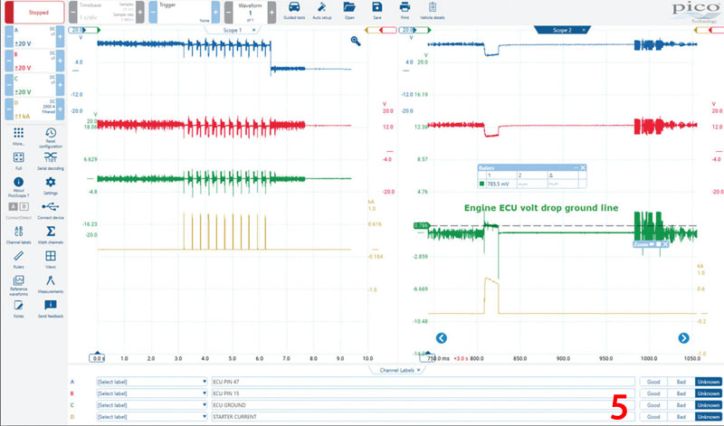
During the starter motor peak inrush (Channel D), we captured an average volt drop of 785 mV. I initially thought that was high, however, the addition of a ground “jump lead” did not change this value. We also knew that the engine ECU was capable of running the engine during the relay bypass test, which removed any doubt surrounding external earthing.
Armed with the confidence generated by the previous tests, we had to test the CAN network at the engine ECU under the fault condition. (Remember multiple ECUs were reporting a loss of communication with the engine ECU.)
Fig.6 captures CAN Lo during the intermittent cranking symptom accompanied by a simultaneous loss of communication to the connected scan tool (monitoring engine ECU live data) and the flickering of the engine MIL.
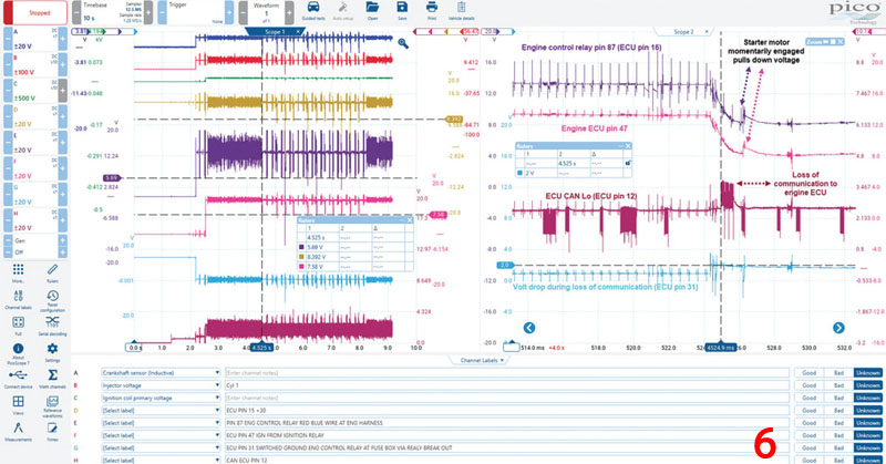
Note how the voltage drops to approximately 8 volts during the momentary operation of the starter motor (Channels E and F). This is to be expected during the initial inrush of the starter motor current. However, this is repeated at approximately 300 ms intervals, which generates huge amounts of noise in the engine control circuits (Channel E).
While these voltages appear to remain at an expected level during the “inrush” at our external measurement points, they also supply other actuators (e.g. the throttle motor) via internal electronics in the engine ECU. (Refer to A177 in the Autodata wiring diagram).
It was noted that, periodically, during intermittent cranking, the throttle motor would appear to “whine” which could suggest a cyclic control of the power supply from inside the engine ECU. Note the back EMF present on Channel E which is characteristic of stop/start motor assemblies (think of inductive spikes from fuel injector coils).
Channel G revealed an increased voltage drop (2V) at ECU pin 31 (which is responsible for grounding the engine control relay), accompanied by some very strange behaviour of our CAN Lo signal on Channel H which appeared to momentarily switch from CAN Lo to CAN Hi! It was at this precise point that communication was lost with the scan tool…
Read next month’s issue to find out what was causing the erratic signals and Steve’s ultimate diagnosis.


