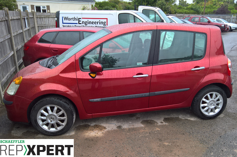
A full clutch replacement guide for a 2005 Renault Modus, which was fitted with a 1.4 (K4J770) petrol engine, had covered more than 60,000 miles and suffered from clutch judder.
Step-by-step procedure
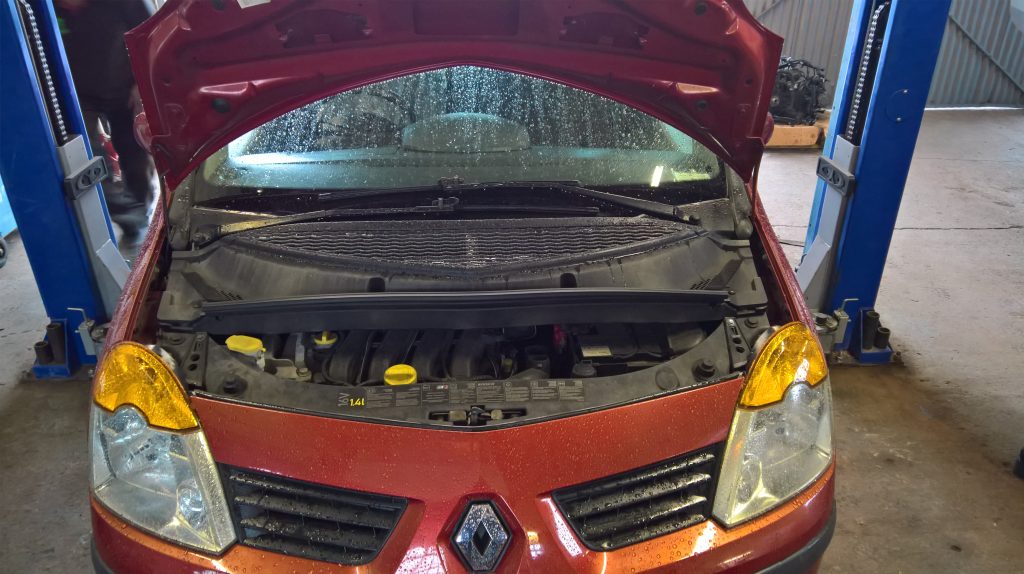
With the vehicle on the ramp, open the bonnet and start by removing the engine bay windscreen trims (see below) – with these trims removed, there is greater access to the gearbox. Now remove the air intake hose, battery, plastic battery surround, complete air filter assembly and then the battery carrier.
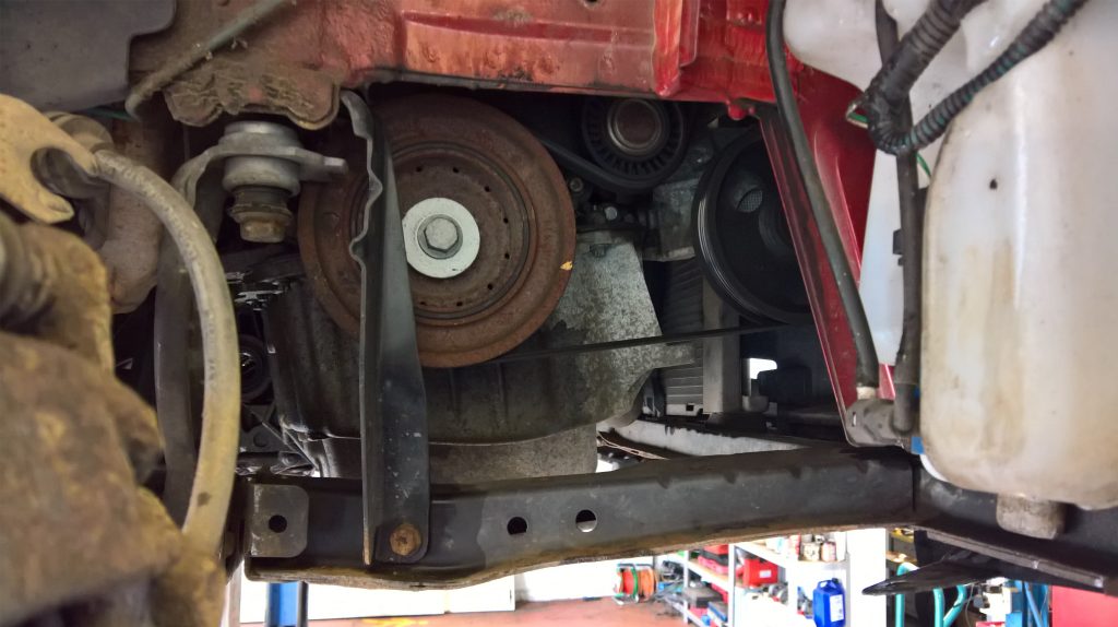
With the vehicle still on the ground, remove the wheel trims and slacken the wheel bolts. Slacken both front hub nuts, raise the ramp to waist height, remove the gearbox oil drain plug, drain the gearbox oil (see below), and then remove both front wheels. Next, remove both front wheel arch liners, remove both front hub nuts and both bottom ball joint pinch bolts. Then, disconnect the ball joints from the hub assembly by levering down the lower suspension arms and swivel out the hub assemblies. Remove the driveshafts from the hub assemblies, allowing the N/S/F inner driveshaft joint to pull clear of the gearbox.

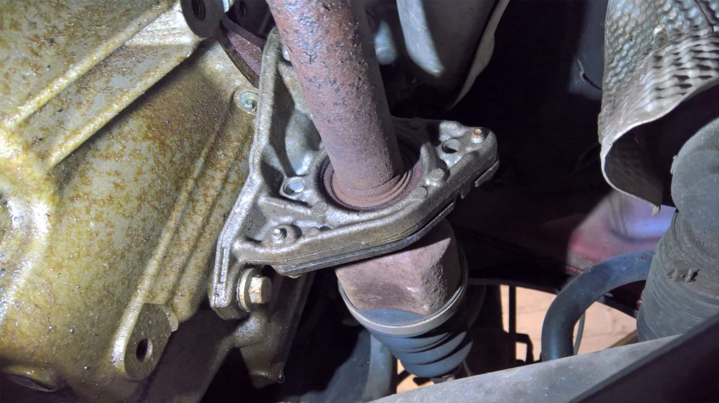
The centre bearing needs to be released from its carrier (see below) – the driveshaft can then be removed.
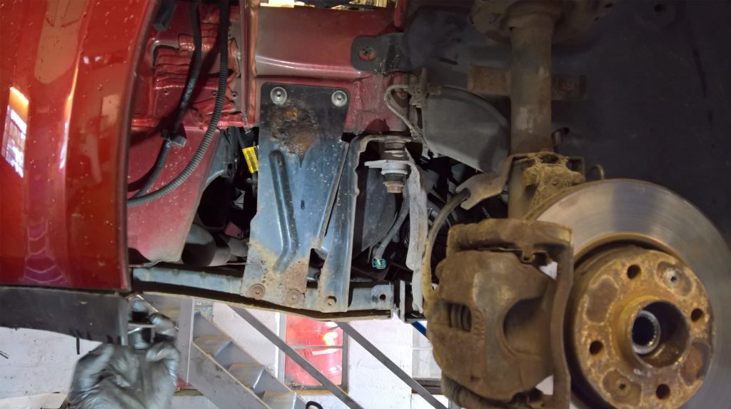
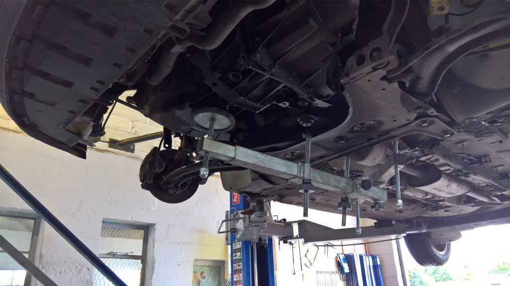
Now remove the supporting brackets from the front sub-frame and the vehicle body on both sides (see below). Support the sub-frame, remove the nuts from the additional brackets and the support bolts at the front of the sub-frame. Lower the front sub-frame and disconnect the lower radiator mountings.
Subsequently, the front sub-frame can be removed and stored in a safe location. Remove the engine/gearbox torque mount. At this point, the engine needs to be supported using an associated subframe attach support, which allows the raising and lowering of the ramp without effecting the engine support (see below).
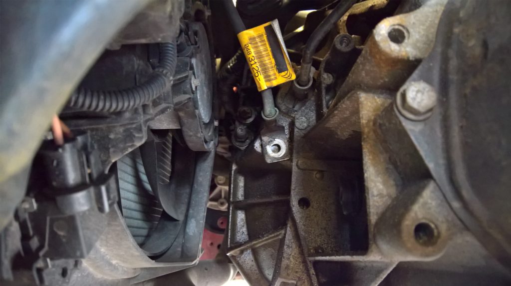
With the engine support fitted, lower the ramp to waist height and disconnect the reverse light switch plug – the reverse light switch was removed to avoid any damage when removing the gearbox. Disconnect the earth cable (see below), and disconnect the starter motor cables. At this point, the lower bell housing bolts can be removed, leaving the two nuts positioned at 3 o’clock and 9 o’clock. The starter motor can also be released from the bell housing.
Next, lower the ramp to the floor, in order to gain access to the top of the gearbox. Remove the top mounting plate for the gearbox mounting and then remove the lower section of the mounting from the gearbox. Subsequently, the clutch pipe can then be disconnected from the concentric slave cylinder and blanked to retain the clutch fluid.
Remove the gear change cables and stow in the bulk head area. Release and ease the engine wiring loom back from the bell housing area to gain access to the top bell housing bolts, which can then be removed. Raise the ramp and support the gearbox with a transmission jack, before removing the two remaining bell housing nuts and removing the mounting studs using a TORX attachment. As a result, the gearbox can then be eased away from the engine and, once the gearbox input shaft is clear of the clutch assembly, the gearbox can be lowered and removed from the vehicle.
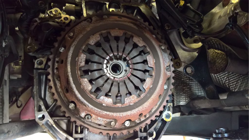
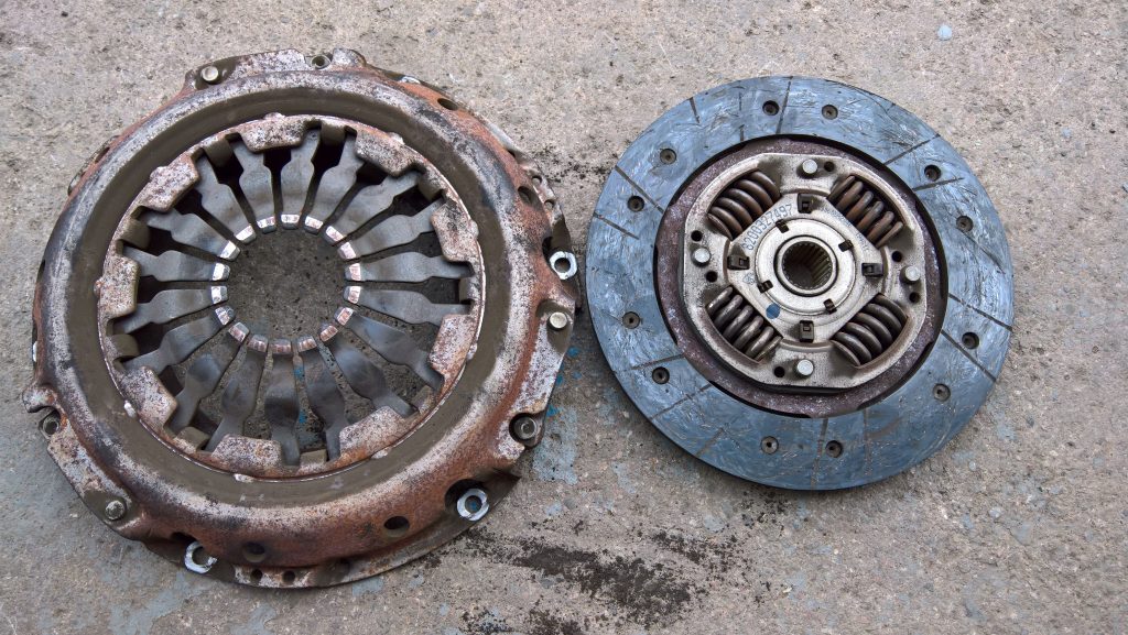
The clutch can then be removed from the flywheel (see below) and be inspected. On this occasion, the root cause of the clutch judder was identified as the clutch system being rusty and dry, with no lubrication, thus not giving a smooth release. The clutch plate had also reached the end of its service life; the lining was nearly level with the metal rivets. The flywheel was inspected for heat and stress cracks, with no evidence of either. Clean the flywheel face with Emory cloth to remove the surface glaze, then clean the flywheel and back of the engine to remove the old clutch dust with brake and clutch dust cleaner.
Remove the old concentric slave cylinder (CSC) from the gearbox bell housing, clean the bell housing with brake and clutch dust cleaner – so as not to contaminate the new clutch system with old clutch dust. Once cleaned, fit the new CSC, ensuring the mating surface is clean so it seats squarely.
Additionally, never ‘dry squeeze’ the new CSC before fitting, as this can cause damage to the new unit. Next, lightly smear highmelting point grease on the splines of the gearbox input shaft. Insert the new clutch plate onto the input shaft. This ensures the splines are the correct fitment and evenly distributes the grease. Remove the clutch plate and wipe off any excess grease. Then, fit the new clutch to the flywheel. Use a universal clutch alignment tool to clamp the clutch plate to the pressure plate/cover in a central position (see below).
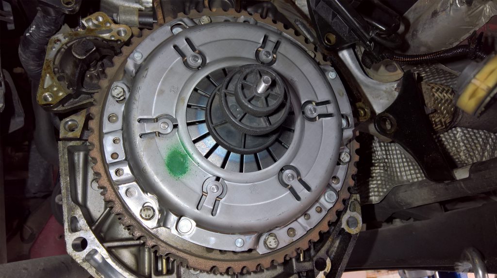
To ensure the clutch plate is fitted correctly, ‘Gearbox Side’ or ‘Getriebe Seite’ is marked on one side, near the centre of the clutch plate. When installing the clutch, tighten the bolts evenly and sequentially – to avoid distorting the new clutch – and torque to the manufacturer’s specification.
Before fitting the gearbox, it is good practice to flush the old clutch fluid out of the clutch system and replace with new fluid, to eliminate the risk of contaminating the new seal in the CSC. This is done easily by placing a drain tray under the clutch pipe and allowing the old fluid to run out of the system, topping up with new fluid until the new fluid runs through. Once flushed, reseal the clutch pipe – ready for gearbox installation.
Finally, before refitting the gearbox, ensure the alignment dowels are located correctly, and refit the gearbox carefully, ensuring correct alignment is achieved. Once in position, installation is in reverse order of removal, torqueing the bolts to the manufacturer’s specification as required. Gravity bleed the clutch – open the bleed system, allowing the air to pass through and re-sealing when the air has dispersed. When the repair is complete and the battery reconnected, reset all electrical systems and
carry out a full road test.


