PMM ’s diagnostics expert, Ben Johnson investigates a PT-CAN 2 failure on a vehicle perhaps a little too close to home…
The morning was crisp and chilly, but nothing could dampen my spirits as I prepared to hit the road in my trusty BMW i3. However, as I reached for my phone to send the preheat command, I was greeted with a strange check control message on the “My BMW” app. Curiosity and concern gripped me, and I quickly wrapped myself up in my warm work gear to investigate the issue.
As I stepped outside, the freezing Finnish winter hit me like a tonne of bricks, and I was grateful for the advanced heat pump preheater system in my electric car. However, my heart sank as I looked at the frosted windows of my i3 and realised that it had failed to preheat the cabin; my worries only multiplied when I saw the myriad of warnings on the instrument cluster, including a troubling “powertrain fault” message. What’s more, the cooling fan was going at full speed, which made no sense in such freezing temperatures. I knew that a check control message combined with the fan coming on usually meant serious trouble – and on the i3, that meant serious money. For instance, replacing the EME – the electrical machine electronics unit that powers the vehicle – could cost upwards of five and a half thousand euros. Ouch! I kept my fingers crossed as I sat inside.
As I attempted a quick, initial diagnosis, my fears were confirmed when the gear selector near the steering wheel – known as the GWS – refused to budge. Panic set in as I realised I couldn’t select forward or reverse, and with no manual release available, my only option was to call a tow truck. It was a frustrating and disappointing experience, especially for a car that was only four years old. I couldn’t help but think of the simplicity and reliability of the trusty Diesel 5 series that I owned prior to purchasing the i3, which had been flawless up to 350,000 km.
Within an hour of my distress call, the tow truck arrived. The driver was friendly and eager to help, but as he began to winch my i3 onto the truck, I was horrified. I knew that the locking pawl system in my car required a different approach. With a heavy heart, I explained to the driver that the i3 needed to be winched on with dollies under the rear wheel. Nobody likes to tell somebody how to do their job but needs must, at times.
To his credit, the driver took my instructions in stride and quickly made the necessary adjustments. Despite my frustration and disappointment with my car’s failure, I couldn’t help but feel grateful for the kind and understanding tow truck driver who went out of his way to help me.
Getting started
The journey from my home to Schmiedmann, a distance of about 50 kilometres, was a breeze despite the snowy weather. We arrived in no time, and the car was promptly pushed to the side of the diagnostics ramp.
After a long day of work, I finally had the chance to inspect my little i3 and read the fault codes. I was determined to get to the bottom of what had gone wrong with my pocket rocket.
As I scrolled through the long list of fault codes, one in particular caught my eye – the PT-CAN 2 bus. This bus was meant to serve as a backup to the main PT-CAN bus, but it was reporting missing messages and the main failure was “PT-CAN 2 open circuit.”.
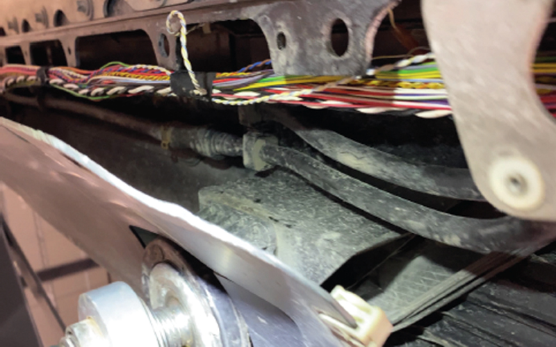
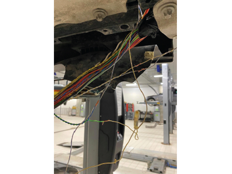
Based on my experience with the i3, I suspected that the issue might be originating from the front left wheel arch. This was a known fault in the i3, as the main vehicle harness is routed outside of the car, over the front subframe, and down to the back subframe inside the chassis rail cavity. While this design might work in the milder Bavarian weather, it is wholly unsuited to the salty and harsh Finnish roads. It was only a matter of time before something went wrong.
When I removed the “frunk” storage box in the i3, I uncovered a useful harness connector on the bulkhead that contained all the buses, including PT-CAN 2, flexray, and more. I quickly took a measurement and discovered a healthy 120 Ohms. I felt relieved, as it seemed that the issue was an intermittent open circuit on the main line of the PT-CAN 2. Following the wiring diagram led me to the realisation that the terminating resistors were located in the EME and the GWS. I would have been more worried to find 60 Ohms at this point as it might have meant a dreaded control unit failure of some sort.
Access challenges
Although the i3 is not a complicated car and contains only a handful of control units, the mountains of harness tape, zip ties, and plastic conduits that are fitted throughout can pose a challenge, especially in hard-to-reach places. However, finding the problem with the CAN bus open circuits was not too difficult, even on the main line. The only issue was that with the car on the ramp, accessing the two and a half metres of wiring in the main harness was proving to be quite a challenge due to the ramp legs getting in the way.
Undeterred, I came up with a solution by devising a bungee cord setup that allowed me to pull the loosened lower sill trim and anchor it to the ramp legs, giving me the space I needed to access the wiring. It was a bit of a makeshift solution, but it did the trick, and soon enough, I was able to decide where to make a start.
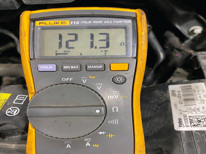
After removing the main line connector, I was able to take a measurement from this point and trace it back into the car to the GWS. This test confirmed that I had a solid reading of 120 Ohms (Fig.1), so I decided to eliminate this wiring from further checks, saving me the trouble of having to inspect an additional 2 m of wiring. I put the connector back temporarily.
Working again
After going for a quick coffee break, I returned to find that the car had seemingly fixed itself like magic. I then disconnected the HV interlock loop again, put the car into safe mode and tested the CAN resistance – 60 Ohms were measured, signifying an intact bus. The main line had seemingly restored itself, and to my delight, the car started working again flawlessly. It selected gear with no issues and there were no check control messages to worry about. That’s when the real fun began!
Any experienced diagnostics technician will tell you that there’s no such thing as a problem that fixes itself. In fact, for us, this is the worst-case scenario because a permanent fault has now become a sporadic one, which can be incredibly challenging to solve. Tracking down these types of issues can take up a significant amount of time!
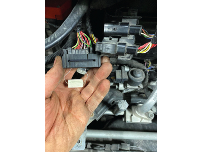
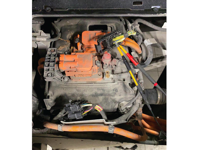
Knowing this, I removed the frunk area harness connector once again and inserted a 120 Ohm resistor into the harness leading to the main harness and back to the EME (Fig.2). This restored the circuit and simulated the GWS being plugged in once more.
To investigate further, I stripped back some of the CAN harness and inserted piercing probes, then set up the Fluke to measure the resistance. Surprisingly, I had 120 Ohms, and nothing worse than that. I twisted, pulled, and moved the harness around, but it didn’t change anything on the Fluke meter display.
With no visible issues in the front left wheel arch area, I decided to measure to the rear of the car and measure from the aft wheel arch to the EME. I made a cut in the main line to do this. At first, I found an immediate 120 Ohms, which was a good sign. However, my joy was short-lived as I began to get some strange sporadic readings.
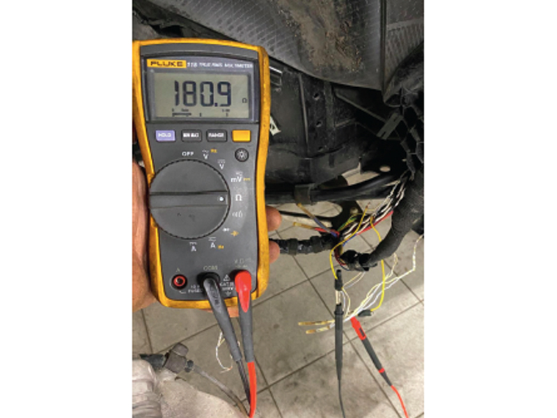
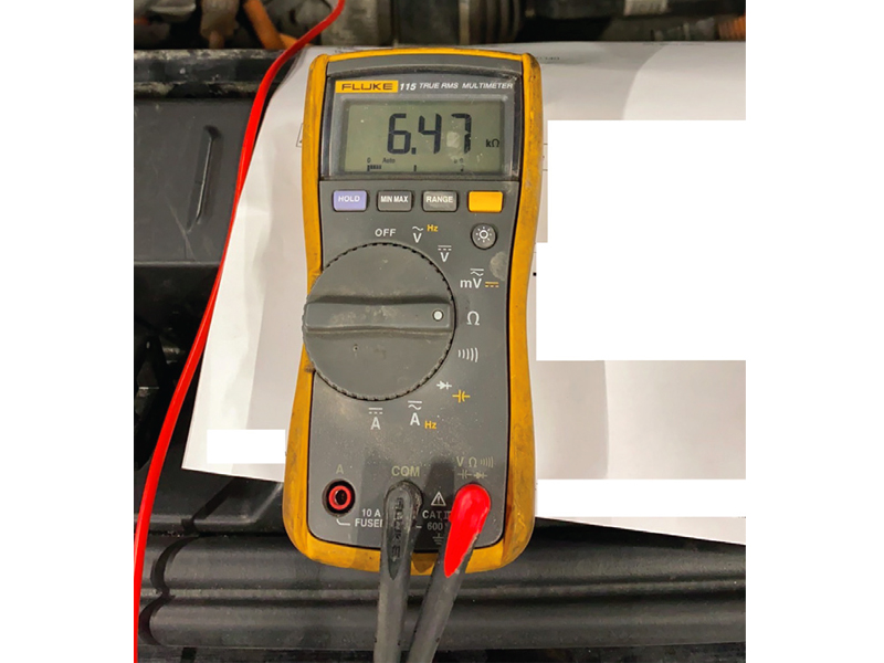
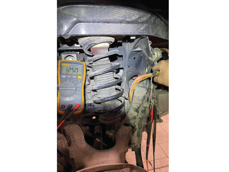
At one point, I even had an unusual kOhm value. I knew then that I was dealing with a bad wire, but the question was where? During the sporadic episode I found that I had 180 Ohms. I had now ticked off the front part of the harness from the aft of the wheel arch to the GWS. I had around three metres or so of wiring to check from the aft wheel arch back to the EME (Figs.3-5).
I realised that the faulty wire was somewhere in the main harness, which meant that finding it was going to be a challenge.
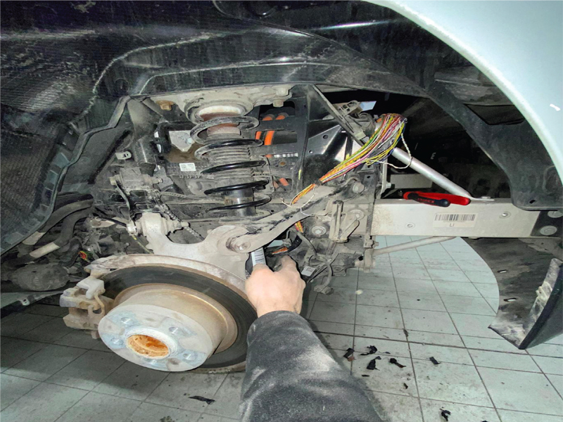
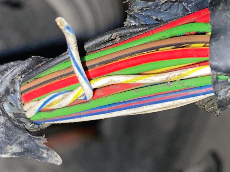
In the back subframe area, I noticed that the branch lines were unfortunately running alongside the main line, making it challenging to distinguish which of the eight wires was the main line and which were the branch lines, especially since the colours were the same. After some intense focus, I managed to solve the problem, but it wasn’t easy. By twisting the wiring harness in the trunk area, I determined that the wire break was located between the trunk and the rear shock absorber. All of my previous testing went out the window. I then exposed all of the CAN wires that had the same colour at the front wheel arch and found seven clean copper wires and one that was blackened.
The same results were found when I repeated this process at the rear shock absorber area: a black wire (Fig.7).
Temporary wire
Running in a temporary wire and restoring the GWS to the main harness ensured that the problem was solved. I had 60 Ohms and the car worked flawlessly. All that remained was to make a new twisted pair which ended up around four metres long (Fig.8). On top of that I designed a much better conduit and taped metres of wiring tighter and most importantly waterproofed as much of it as possible. I even used some coolant hose as a flexible conduit in the worst exposed area – the rear subframe. All that remained was to build it up and check the PT-CAN 2 signal on the AVI scope. Result was a good signal. One thing that I am never annoyed about is even though the job was very stressful, being my own car, I learned more about the architecture of the i3 during the experience than I had ever learned before. The car is now running well and ready for the daily commute.
And the wire? Well, finding the exact area of concern proved time consuming but I found one part of the CAN wiring severed in two pieces and it had been making and breaking a connection for some time, perhaps even a year or two until the ingress of moisture started to cause such deep corrosion that it eventually caused the wire to break completely. What is always staggering to me is that even with such a high resistance CAN messaging was still able to get past it. Quite incredible, I think and a testament to just how robust the CAN protocol is.


