In the first part of this feature, Pico technician Steve Smith tackles an Audi Q7 e-tron which is failing to charge.
Vehicle Information
Manufacturer: Audi
Model: Q7 e-tron Hybrid
Year: 2017
Model code: 4M
Engine code: CVZA (3.0 TDI V6)
Transmission: ZF 8-Speed Automatic
Mileage: 33,406 miles
Failed part: On-board Charger (OBC)
Customer’s description
The vehicle fails to charge from the mains charger unit supplied with the vehicle. Such charging methods are referred to “Mode 2 charging” and utilise the domestic mains supply via a 3-pin plug. Their typical consumption is around 10 A with a power output of approx. 2.2 kW.
Technical description
Verifying the customer complaint is an essential step in the diagnostic process but quite often a time-consuming task without success. On this occasion, the fault was apparent using either the owner’s charger unit or “Mode 3 charging”, which refers to an AC wall mounted charging pod with a consumption rate of 32 A and power output of 7.2 kW Upon connection of the Type 2 charging plug to the vehicle, the charge inlet locking pin could be heard to cycle three times before a red warning LED would illuminate to inform the owner of a charging error.
The vehicle instrumentation recognised connection of the mains charger, however charging would not commence.
Note: Whilst mains charging was inoperative, the HV battery could be charged by running the engine until sufficient charge could be achieved to drive the vehicle a short distance on electric alone. We can therefore surmise the battery can accept charge and deliver sufficient current to power the electric drive motor.
Diagnosis
With the customer complaint verified, the Vehicle’s ID and Specification were confirmed. Confirmation of vehicle specification is of the utmost importance when it comes to diagnosis as there is often a temptation for customers to modify their car with fashionable accessories that lack the fundamental quality control and engineering that was intended for the vehicle. A brief evaluation of the vehicle did not reveal any concerns in the form of aftermarket accessories; however, it was discovered the vehicle had been purchased from an auction and so questioning the original owner was not possible.
The Customer Interview follows the four “targeted” open question principle below in order to establish facts from fiction.
How long has the problem been evident?
Vehicle recently purchased from an auction with the fault evident
When did you first notice the problem?
Upon purchase
Has any work been carried out on the vehicle recently?
No history supplied with the vehicle on purchase and no access to previous owner. A new charge inlet socket complete with cabling and locking pin had been installed since purchase
When do you experience the problem?
When attempting to charge the HV battery via Mode 2 or 3 charging.
Based on the above, we have very little to go on in terms of historical facts which often provide essential clues to accompany symptoms. Not to worry, let’s march on.
The Basic Inspection confirmed no fluid leakages, no visible signs of damage to hoses, connections, wiring harnesses or indeed that favourite discovery, “accident repair”.
A vehicle scan of all on board control units revealed multiple fault codes, including the code of relevance to HV charging, “Charging Socket A; Charging Plug Lock P33E8 00 [008] – Mechanical Malfunction”. Additional data surrounding this fault code can be seen in Fig.1.
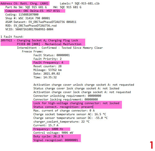
To summarise the data: “AX4” is the VAG code for On Board Charger (OBC) which has reported a mechanical problem with the lock pin designed to lock the Type 2 charger plug into the charge inlet socket. In addition, a number of parameters have been stored at the time of fault code detection (i.e., Freeze frame data) – so what do these parameters reveal?
Fault status 00000001: Fault is present
Fault frequency 4: Four detected events of this fault
Lock for high-voltage charging connector not locked: OBC can detect charging plug is not locked (should be “locked”)
Status connect. recognition: present: OBC can detect presence of charging plug via Proximity circuit (PP)
Max. current of charge connector: 0 A: Charging is not taking place as we have no current flow
Charge sensor temperature sensor DC: – 55.0°C: Default charge socket temperature value as DC charging is not applicable
Current: 15.7 A: Charging current available from the connected charger (communicated to the OBC)
Frequency: 1,000 Hz: Frequency of Control Pilot (CP) PWM signal
Control voltage: 9006 mV: CP Line voltage at peak of + 9 V suggesting OBC has paired with mains charger but not charging (normally peak of + 6 V when charging)
Duty cycle: 26.2%: Positive duty cycle of Control Pilot (CP) PWM signal (26.2 % approx. 16 A charge current available) Signal recognised: 00000001: OBC can detect charger plug connection and interprets charge information relayed from charger (via CP)
From the above freeze frame data, we can conclude the OBC is detecting the presence of a charging plug and CP/PP lines appear to be interpreted correctly, yet the position of the charge plug lock pin remains “not locked”. Could the failure of the charge plug lock pin result in no charge?
Prior to diving in here, taking a step back and checking for technical bulletins is paramount. None were relevant and so based on the vehicle history and symptoms, we can move on.
Possible causes
- Wiring harness error between Type 2
Charge inlet socket and OBC - Incorrect signals/values relayed between
Charge inlet socket and OBC - Charging inhibited by other on-board systems (Perhaps via CAN messaging)
- Faulty OBC (AX4)
The action plan
The action plan is predominantly governed by accessibility, probability and cost. Based on the acquired fault code and description of the fault, the focus is placed on the Type 2 lock pin circuit:
- Wiggle testing and visual inspection of OBC wiring and connectors
- Measurement of locking pin actuator and position sensor
- “Pin out” testing of all low voltage inputs/outputs at OBC
A variety of trim panels and under-shields were removed for access to the rear of the charge inlet socket, OBC and associated wiring.
Given we are trying to establish the functionality of the Type 2 charger plug lock pin and associated circuits, an element of reverse engineering is required and this is where 8-channels of the PicoScope 4823 come into their own. The advantage here is that we can see how each of our chosen circuits interact with one another in order to evaluate the sequence of events when attempting to charge the vehicle. The disadvantage is that we are applying an 8-channel scope within an HV environment and therefore the appropriate precautions must be adhered too.
Note: The necessary and relevant risk assessment, training, PPE, signage, measurement hardware and best practices are paramount before commencing and during diagnosis so as to ensure the safety of all
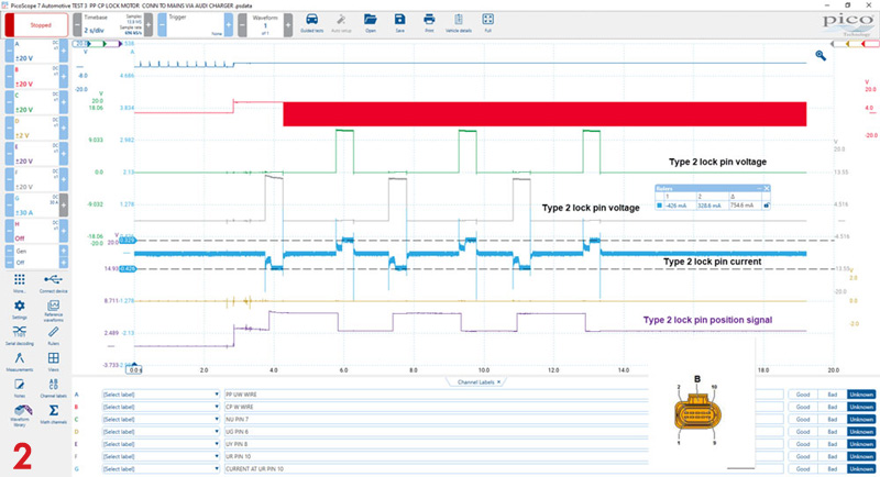
Evaluation of Type 2 charge inlet circuit: Day 1
In Fig.2 we are connected to connector B (THRL) at the rear of the charge inlet socket in order to remotely obtain an overview of the interaction between CP, PP, lock pin actuation and position. Note how the lock pin is “cycled” three times over the entire capture before returning to the disengaged position Let’s break down the capture in Fig.2 into useful data and refer to the capture in Fig.3:
- Channel A displays PP voltage and captures the change of state at the point of charger plug insertions
- Channel B captures the CP line voltage and PWM signal from the mains charger unit to the OBC. Note: The peak positive voltage, frequency and duty of the CP line match the freeze frame data supplied with our DTC P33E8 00 [008]
- Channels C and F measure each side of the lock pin actuator with reference to chassis ground. Note how any differential between these channels results in current flow (lock pin actuation) which is captured on channel G
- Channel D is the ground return from the lock pin position sensor
- Channel E captures the lock pin position voltage. Note how the voltage rests at approx. 3 V with the lock pin disengaged and approx. 6.5 V when engaged. Interestingly the lock pin is then cycled 3 times before coming to rest in the disengaged position. At this point the red warning LED adjacent to the charge inlet illuminates to inform the owner of a charging error. On the surface, everything looks to be normal!
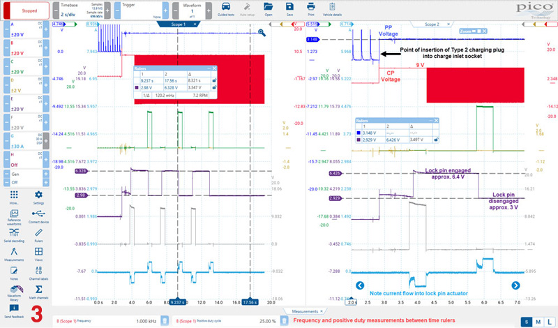
- Our PP line voltage changes to indicate charger plug insertion (also confirmed within freeze frame data)
- Our CP line voltage changes upon charger plug insertion (peak + 9 V) and communication between mains charger/OBC commences with a 1 kHz PWM signal at 25% positive duty (again confirmed within freeze frame data)
- However, in order for charging to commence, our CP line voltage must change from + 9 V .. -12 V to + 6 V ..-12 V and this event does not occur
- Our lock pin position switch informs the OBC of engagement and disengagement
Note: Our lock pin is physically engaging with the charger plug as I could not remove the plug when the pin was momentarily engaged.
The question is, therefore: Why does the vehicle not charge? At this stage I do not know!
Part two will be coming next month, stay tuned to find out what was causing Steve so many problems.


