Following on from part one of this feature, we rejoin PICO Technician Steve Smith as he continues his breakdown of how to locate the intermittent knocking noises coming from a troublesome BMW.
After our series of tests, I think we can agree at this stage the RH front subframe is our area of concern, so the focus now is to zone in further using multiple accelerometers. The subframe provides multiple mounting points and components on which to ‘plot’ the journey of our knocking noise; one such component is the steering rack assembly.
Revised accelerometer locations
Engine off steering wheel rocked
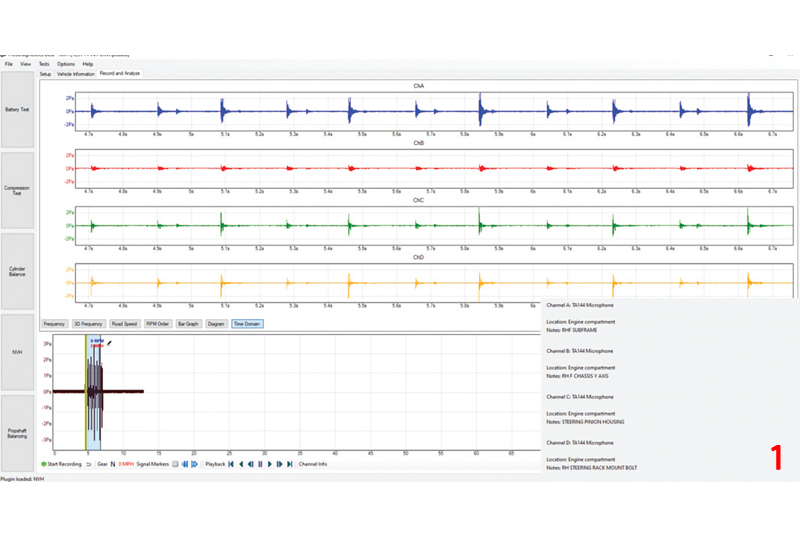
- Channel A (Blue): RH front subframe
- Channel B (Red): RH front chassis
- Channel C (Green): Steering rack pinion housing
- Channel D (Yellow): RH steering rack rear mounting bolt
Once again, the results in Fig 1 indicate the accelerometer placed in the RH front subframe is exposed to the highest level of energy generated by the knock – but is it the first responder? Let’s take a closer look, with PicoScope (Fig 2).
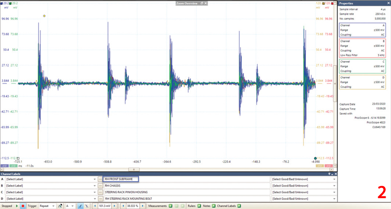
Clearly, the capture shows that the RH Front Subframe has the greater amplitude during the ‘knock event’.
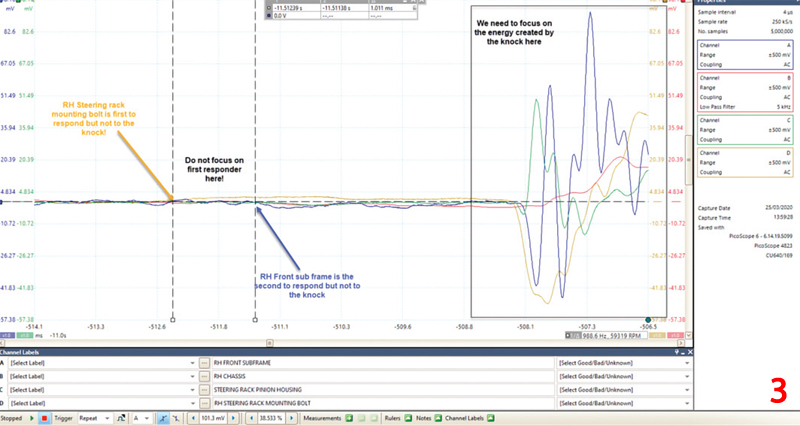
In Fig 3, we zoom in to reveal activity before the knock event that has the potential to disrupt the theory surrounding the first responding accelerometer. Here, the accelerometers are detecting the momentary steering input into the steering rack prior to the generation of the knock. Now, we need to focus on the accelerometer response created by the dramatic increase in energy generated by the knock (referred to as the knock signature) and not the prior events.
Focusing on the knock events in Fig 4 and measuring the response time of each accelerometer, we can now see the response order has changed.
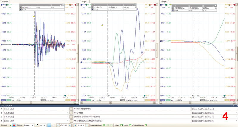
Response order to knock signature:
- First: RH steering rack rear mounting bolt
- Second: Steering rack pinion housing
- Third: RH front subframe
- Fourth: RH front chassis
Given that we know the root cause of our steering knock (BMW Technical bulletin), I thought it would be interesting to understand how and why this knock can be felt in the steering wheel. Whilst we know our knock is generated inside the steering gear between the rack and pinion, we also have a steering column intermediate shaft with two universal joints to consider. We can eliminate the intermediate shaft from our diagnosis using accelerometers.
Revised accelerometer locations
Engine off steering wheel rocked (Fig 5)
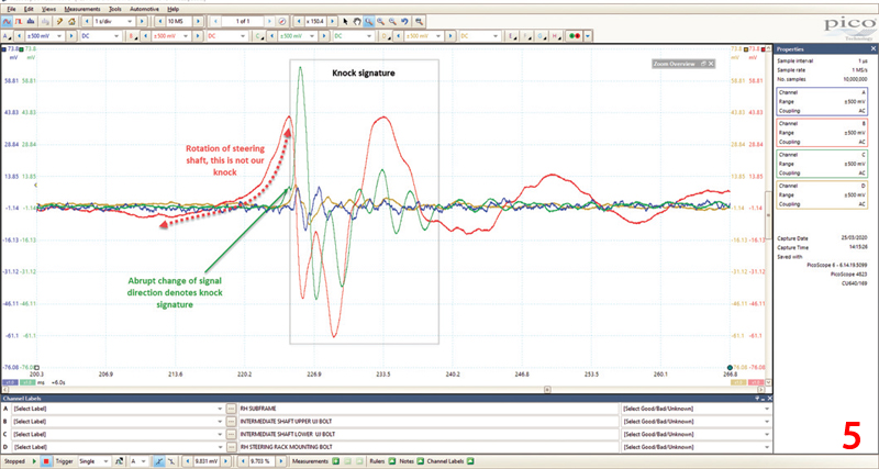
- Channel A (Blue): RH front subframe
- Channel B (Red): Steering column intermediate shaft upper UJ
- Channel C (Green): Steering column intermediate shaft lower UJ
- Channel D (Yellow): RH steering rack rear mounting bolt
In Fig 6, we have the engine off but steering wheel rotated approx. 20° back and forth.
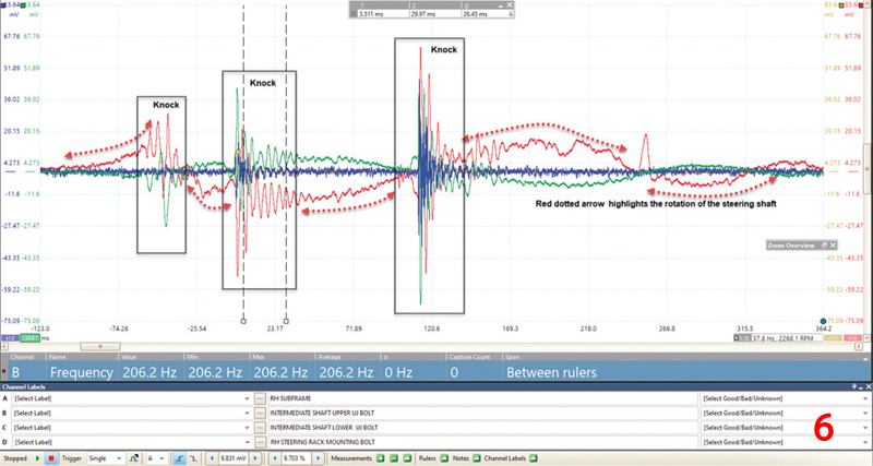
Here, we have to ignore the first response from the red accelerometer as we are detecting rotation of the intermediate shaft. The knock signature has been ‘complicated’ by the rotation of the steering shaft, however, the RH steering rack mounting and RH front subframe are once again early responders, suggesting our knock does not originate from the intermediate shaft (Fig 7).
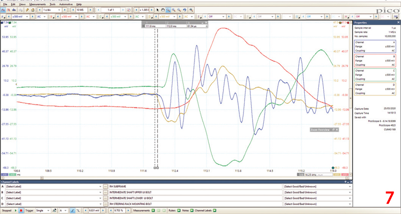
Response order to knock signature:
- First: RH steering rack rear mounting bolt
- Second: RH front subframe
- Third: Steering column intermediate shaft lower UJ
- Fourth: Steering column intermediate shaft upper UJ
So, we know that the RH steering rack mounting bolt, RH subframe and steering rack pinion housing are all first responders and we can discard the intermediate shaft and LH side of the chassis/subframe. A final measurement was therefore taken at the RH side of the steering gear and the underside of the steering rack pinon housing.
Note: when attaching the magnetic accelerometer to the aluminium steering gear a steel washer was bonded in place using ‘Bondloc’.
Revised accelerometer locations
Engine off steering wheel rocked
- Channel A (Blue): Bonded to the underside of steering rack pinion housing
- Channel B (Red): RH steering rack front mounting bolt
- Channel C (Green): Steering rack pinion housing
- Channel D (Yellow): RH steering rack rear mounting bolt
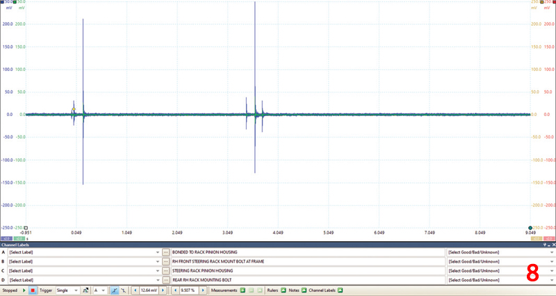
First impressions of Fig 8 suggest that we have found the epicentre of our knock based on the instantaneous and dramatic response of the accelerometer bonded to the user side of the steering rack pinion housing.
In Fig 9, we zoom in on this capture to reveal the response times.
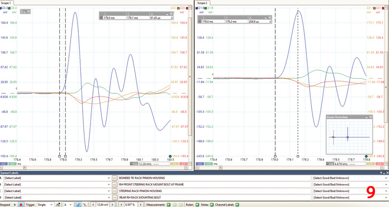
Response order to knock signature:
- First: Bonded to the underside of steering rack pinon housing (0 seconds)
- Second: RH steering rack front mounting bolt (81.43μs)
- Third: RH steering rack rear mounting bolt (81.43μs)
- Fourth: Steering rack pinion housing (204.9μs)
I have added the response timings above of all accelerometers beginning with the first responding accelerometer (0 seconds) through to the final responder at 204.9μs. Note how the accelerometers attached to the steering rack mounting bolts responded together instantly due to them being attached equally about the steering rack pinion housing.
Results
Based on the collective results and response times of our accelerometer tests throughout this study (in relation to the steering knock), we conclude the following response order:
- Steering rack pinion housing (lower) – This is the origin of the knock
- Steering rack mounting bolts
- Steering rack pinion housing (upper)
- RH front subframe
- LH front subframe
- RH chassis
- LH chassis
Repair procedure
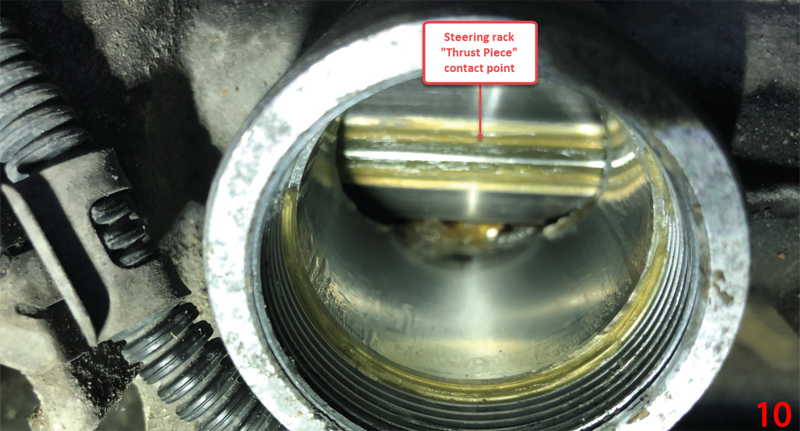
Following the workshop manual, the steering rack thrust piece was replaced and ‘loaded’ accordingly to ensure minimal backlash between the steering rack and pinion (Fig 10).
Confirmation of repair
The proof is most certainly in the pudding and confirmation of repair is often a procedure that is overlooked or sacrificed due to time constraints. Post-fix measurements provide further objective evidence that protects all parties involved and ensures confidence during the customer hand over.
Never has it been more important to qualify any repair we carry out than with complaints of noise or vibration as they can be a matter of opinion and scientific measurements are needed as proof. When carrying out post-fix confirmation, ensure all variables are kept to a minimum and be sure to match the pre- and post-fix test conditions where possible.
Revised accelerometer locations
Engine off steering wheel rocked fix
- Channel A (Blue): Bonded to the underside of steering rack pinion housing
- Channel B (Red): Steering column intermediate shaft upper UJ (to indicate ‘rocking’ motion)
- Channel C (Green): Steering rack pinion housing
- Channel D (Yellow): RH steering rack rear mounting bolt
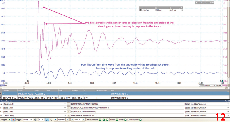
In Fig 11, we can see a completely different response from the accelerometer bonded to the underside of the steering rack pinion housing. The amplitude has reduced dramatically and the response from the accelerometer demonstrates a uniform sine wave (responding to the steering rack rocking motion), rather than the sporadic and instantaneous acceleration in response to the previous knock. Note that the red accelerometer has purposely been attached to the steering column intermediate shaft to denote ‘first motion’ of the steering as there is no longer a knock signature for reference.
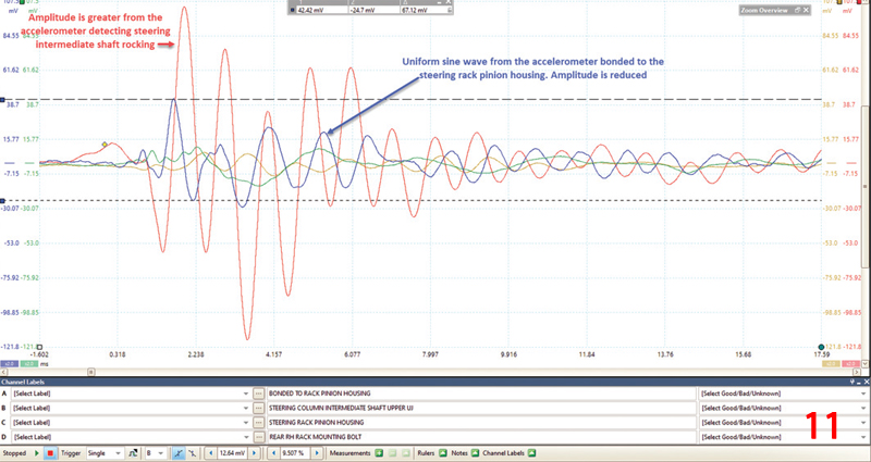
Fig 12 is a reference waveform of the steering knock captured from the accelerometer bonded to the underside of the steering rack pinon housing pre and post fix. The waveforms speak for themselves and can serve as objective data for the customer.
Additional comments
Regarding our post-fix handover to the customer, when rocking the steering wheel back and forth without EPS intervention, there will inevitably be some form of noise due to the loading of the steering gear from the tyre contact with the road surface. The wider the cross-sectional area of the tyre the greater the loading and this must not be confused with the backlash noise creating the steering knock. Capturing pre and post data will reinforce the integrity of the repair while enabling you to demonstrate to the customer the difference between both.
Conclusion
Whilst the nature of the steering fault was known from the start, the technique described above will assist with knock detection and highlight a number of analysis features both in Pico Diagnostics (NVH) and PicoScope. In most cases, the accelerometers were positioned in a near vertical orientation and only the Y axis was captured/measured, however, any axis could have been used to capture the knock.
Bear in mind that the energy created by the knock will travel in all directions – think of ripples on a pond after throwing a stone into the water. The accelerometer would detect the knock in any chosen (X, Y or Z axis), but remember for best results, mount all accelerometers in the same orientation and measure the same axis.


