In the second part of this feature, Pico technician Steve Smith resolves the problem causing an Audi Q7 e-tron charging issues.
Vehicle Information
Manufacturer: Audi
Model: Q7 e-tron Hybrid
Year: 2017
Model code: 4M
Engine code: CVZA (3.0 TDI V6)
Transmission: ZF 8-Speed Automatic
Mileage: 33,406 miles
Failed part: On-board Charger (OBC)
Recap
The vehicle fails to charge from the mains charger unit supplied with the vehicle. Upon connection of the Type 2 charging plug to the vehicle, the charge inlet locking pin could be heard to cycle three times before a red warning LED would illuminate to inform the owner of a charging error.
Let’s continue…
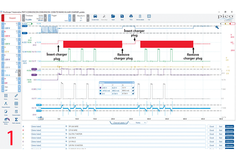
In Fig.1/main image we have an identical test to the previous ones but over a longer time frame to demonstrate how the symptom does not change – i.e. the lock pin cycles three times after each insertion of the charger plug into the vehicle inlet.
Based on the fault code description “Charging Socket A; Charging Plug Lock P33E8 00 [008] – Mechanical Malfunction” I could not see how such a description could apply to a lock pin that is working correctly and physical engaging with the lock plug.
Why would the OBC report a mechanical error with a functioning lock pin and more importantly, how does it know the lock pin has failed? The answer has to be related to the lock pin position sensor and associated circuit.
After searching various SSPs and technical data sites I could not locate the relevant literature to take the diagnosis any further. With hindsight, I should have looked for a test plan to accompany fault code P33E8 00 [008], however using back-to-back data from a Mk VII e-Golf seemed like a quick route to establish “real-time” lock pin values.
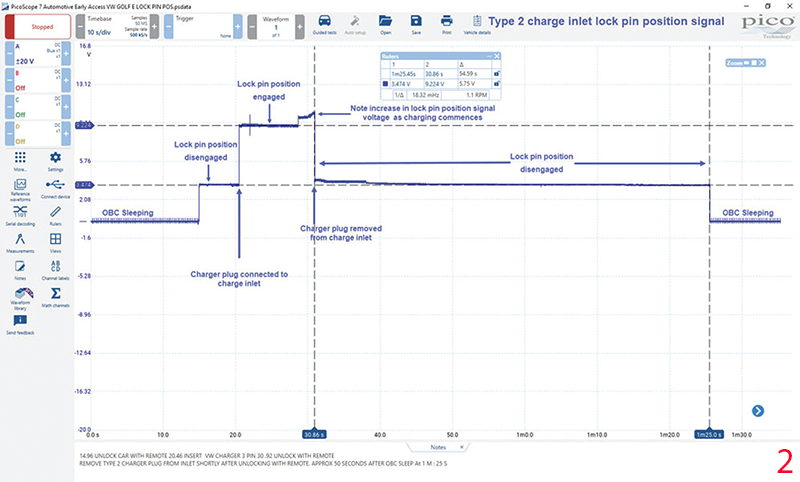
Fig.2 shows the lock pin position signal from a functioning Mk VII e-Golf when a Type 2 charger plug is inserted into the charge inlet. Wow, a breakthrough at last as the lock pin position voltages vary between our e-Golf and Q7 Plug-In Hybrid! Both vehicles return comparable lock pin position voltages when disengaged:
- Q7 lock pin disengaged:Approx. 3V(2.93V)
- e-Golf lock pin disengaged: Approx. 3 V (3.4 V)
However, with the lock pin engaged this is a different story:
- Q7 lock pin engaged: Approx. 3 V (6.23 V)
- e-Golf lock pin disengaged: Approx. 3 V (9.22 V)
If we calculate the voltage differentials between lock and unlocked for both vehicles, we can further understand the discrepancy:
- Q7 lock pin position differential voltage = 6.23 V – 2.93 V = 3.3 V (allowing for variables we can round this down to 3 V)
- e-Golf lock pin position differential voltage = 9.22 V – 3.4 V = 5.82 V (allowing for variables we can round this up to 6 V)
A word to the wise here regarding back-toback testing, “when it’s all you’ve got its all you’ve got”. However, I was not comparing like-for-like vehicles (even though they fall under the VAG umbrella).
I could not find any data to support the expected values for lock pin position voltages and as a result, our only option is comparison testing of numerous similar vehicles (I guess you can call this “spot the difference”).
Armed with the above information I was keen to return to the vehicle and evaluate the lock pin circuit even further. However, the decision had been taken by the customer to install a second-hand OBC. Whilst this is a gamble and a “leap of faith”, the good news was the fault had cleared and the vehicle now charges (that doesn’t happen every day!).
Day Two
To say I was keen to re-measure this vehicle and understand how our values had changed would be an understatement.
Returning to the vehicle, I repeated the initial measurements above and focussed solely on the lock pin position voltages. Note in Fig.3 how the lock pin position values are now closer aligned to those of the e-Golf donor car at 3.3 V disengaged and 9.4 V engaged (differential of 6.1 V).
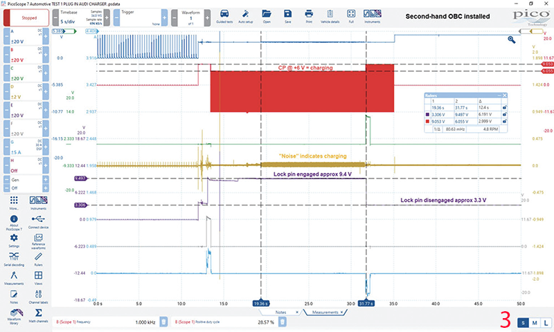
Our CP voltage has now switched to +6 V… -12 V confirming our OBC has now responded to the correct lock pin position and allowed charging to commence.
Channel D (lock pin position signal ground reference) has an increased noise level thanks to the commencement of charging.
Note also how the lock pin is no longer cycled, the pin is engaged upon connection of the charge plug to the charge inlet and this state does not change until the remote key “unlock” button is pressed at approx. 31.77 s where the lock pin disengages and charging is halted.
The positive duty cycle (between the time rulers) is measured at 28.57 per cent suggesting an available charge current of approx. 16 A.
Confirmation of repair
The proof, as they say, is in the pudding and the fact that replacing the OBC resulted in differing lock pin position voltages, the removal of fault code P33E8 00 [008] and vehicle finally charging, confirms our faulty component was indeed the OBC.
Reading back through this case study you would be forgiven for thinking the oscilloscope did not play a part in the diagnosis of the OBC. Indirectly that would be correct but let’s take a look at the bigger picture and what we have learned as a direct result of the oscilloscope’s application.
Using the tool has revealed the interaction between PP, CP and lock pin position relative to “time”.
Not only is the lock pin a desirable security feature, but also an essential input required to both initiate and terminate the charging process.
Until the OBC receives the correct lock pin position voltage (confirming pin engagement) charging will not commence. In the case of the VAG models tested, lock pin differential voltage between disengaged and engaged proved to be approximately 6 V (Please note this may not be the same for all vehicles).
Below we reveal the sequence of events as they occur in time from charge plug insertion to end of charging upon activation of the remote key unlock button (Fig.4).
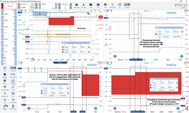
Charging system response to charger connection:
- Activate remote key unlock button
- Charger plug inserted
- PP line voltage changes from pulsed signal to a fixed value dependent upon current rating of charge plug
- CP line voltage changes from 0 V to +9 V peak
- Lock pin position is indicated as fully engaged
- CP line voltage changes to +6 V peak and
- charging can commence
Charging system response to charger disconnection:
- Activate remote key unlock button
- Lock pin actuator is activated
- CP line voltage simultaneously changes to + 9 V peak (charging is halted)
- Lock pin position is indicated as disengaged
- Charger plug removed
- CP line voltage returns to 0 V
Referring now to the charger plug lock pin, I was intrigued to discover how the locking mechanism functioned and, more importantly, how the lock pin position was relayed from the lock pin actuator to the OBC.
Given that a new Type 2 charge inlet socket had been installed, the temptation to dismantle the original unit (complete with lock pin actuator) was too much to resist.
In Fig.5 we have the lock pin actuator mounted directly above the Type 2 charge inlet socket.
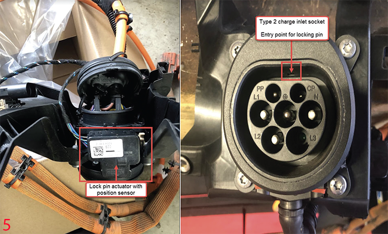
Inside the lock pin actuator, we have a drive motor, gear assembly and a microswitch linked to the locking pin. Note also the two resistors and their relationship to the microswitch (by-pass) (Fig.6&7)
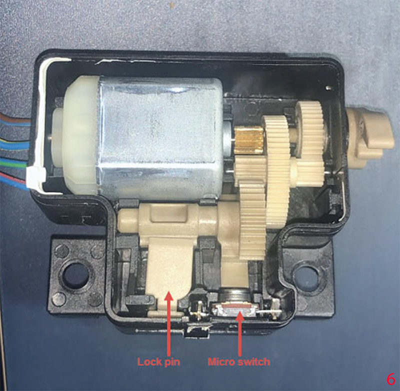
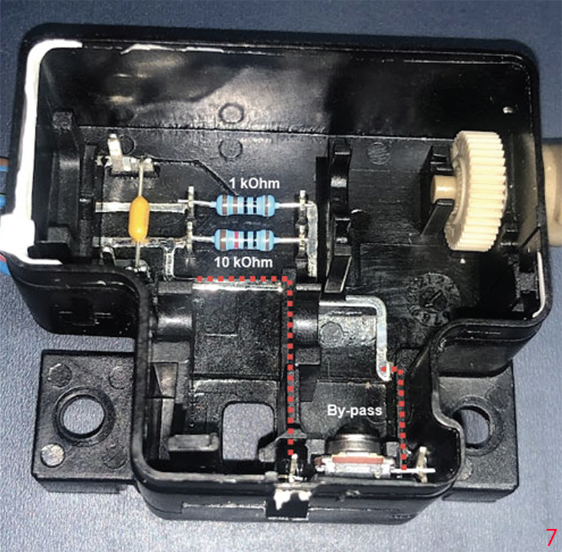
As the lock pin travels through the actuator body, a sector gear linked to a cam acts upon the microswitch. With the lock pin disengaged the total circuit resistance is equal to 11 kΩ as both the 1 kΩ and 10 kΩ resistors are in series. With the lock pin engaged, the rotation of the sector gear and cam close the microswitch, so bypassing the 10 kΩ resister. (Total circuit resistance 1 kΩ).
The change in the resistance of the lock pin position circuit results in our 3.3 V (disengaged) and 9.4 V (engaged) which the OBC utilises to qualify the locking of our charger plug.
The burning question therefore is what has failed inside the OBC which would change the lock pin position signal from 6.23 V to 9.4 V when fully engaged? I don’t have the answer but I will find out when I have permission to dismantle to original OBC.
Thanks to Steve Winn Autocare and Pete Melville at HEVRA for their support.


