Opus IVS, a provider of diagnostics solutions backed by OE master technicians, explains a problem documented for the N12 engine used on 2006 to 2013 second generation Minis, in which the EML warning light shows.
The fault presents with the engine management warning light illuminated and fault code 2968 stored in the digital motor electronics (DME) from the inlet camshaft sensor. This fault can have many possible sensor-related causes. These include a faulty part, an incorrect part being fitted, faulty wiring as well as sensor corrosion or damage. It may also indicate a DME internal fault or an inoperative inlet VANOS unit.
The valve gear on the N12 engine is equipped with variable camshaft timing control for the inlet and exhaust camshafts (also known as double VANOS). Both camshaft sensors record camshaft adjustment, via a sensor wheel fixed to the camshaft.
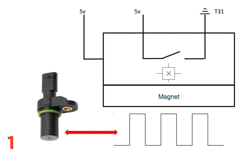
The camshaft sensor works according to the hall effect. Voltage is supplied to the sensor by the DME with 5 volts and ground. The sensor then returns a digital signal via the signal line back to the DME (Fig.1).
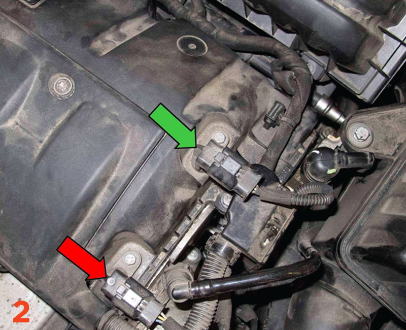
To begin, start by swapping over the inlet camshaft sensor with the exhaust camshaft sensor – they are the exact same part so this is often a very quick task. The fault migrates to the exhaust camshaft then replace the sensor (Fig.2).
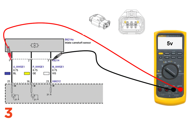
If the fault stays on the inlet camshaft sensor then proceed to check the wiring. You will need a 5 V feed, ground and an intact signal wire between the inlet camshaft sensor and the DME to prove the 5 V supply and earth is being provided by the DME (Fig.3).
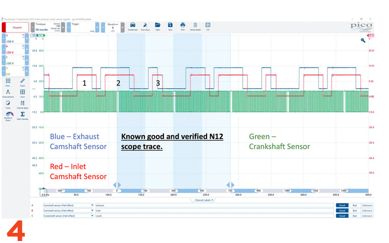
Next, check the signal pattern with an oscilloscope. A signal indicates that the sensor is working whilst scoping at the DME end will also check the integrity of the signal line (Fig.4).
The signals in Fig.4 are correct, from a verified N12 running engine. Both the intake and exhaust camshaft sensors should have an identical scope pattern, just at different positions on the screen. The Opus IVS 360 live support team has seen cases where non- OE or used camshafts have been fitted. When doing so, you must make sure the camshaft is an exact match for the part removed.
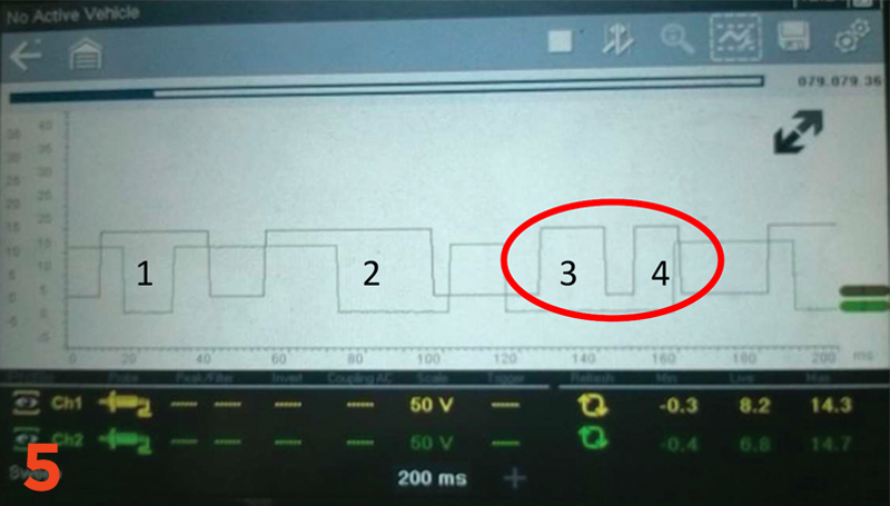
Fig.5 shows the scope trace from an N12 where an incorrect inlet camshaft was fitted. We can see that with this alternative aftermarket part fitted, the inlet camshaft sensor signal has four phases compared to the image on the known good engine with only three.
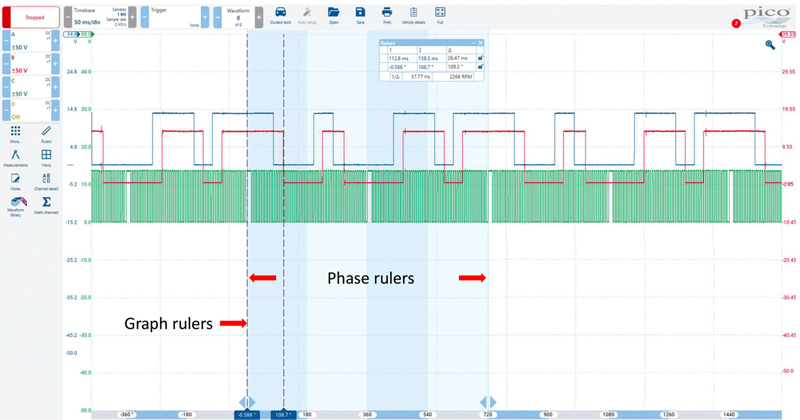
By scoping the inlet camshaft sensor and exhaust camshaft sensor, along with the crankshaft sensor, the timing of the engine can be checked non-intrusively too using phase rulers and graph rulers as shown.


