Doing work for a second-hand car salesman can be a bit… well let’s say annoying at times! Their main concern is their profit and the jobs I receive from car sales plots are often in-depth. What’s more, he/she can be pressurising at times as – in their own mind at least – it’s always a quick fix!
Illuminated lights
This is exactly the scenario when I was presented with a 2001 Mini, which suddenly displayed an illuminated airbag light and tyre pressure monitoring (TPMS) light after the vehicle had undergone a valet. Predictably the salesman’s request when he presented the vehicle to us was: “If you can just plug it in and reset it…….” – how many times do we hear that one?
I had been informed that a mobile company had been out to see to the vehicle already and their diagnostic tool was failing to connect. With the buyer collecting this vehicle at the end of the day the salesman was waiting impatiently. So the only thing for it was to see what I could do on the spot.
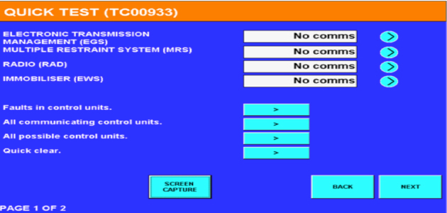
Using my Autologic tool I carried out a quick scan (see screen grab, above); this feature will attempt to connect to every module for that variant. I immediately found that we had no communication for the Multiple Restraint System (MRS), Electronic Transmission Management (EGS), Radio (RAD) and Immobiliser (EWS) – probably the reason why our lights were illuminated.
Using my Autologic tool I carried out a quick scan (see screen grab, above); this feature will attempt to connect to every module for that variant. I immediately found that we had no communication for the Multiple Restraint System (MRS), Electronic Transmission Management (EGS), Radio (RAD) and Immobiliser (EWS) – probably the reason why our lights were illuminated.
Bearing in mind the customer was just interested in the airbag and TPMS warning lights, I then had to ask two questions: a) is this just one fault?; and b) where do we start?
Diagnostic plan
I explained to the salesman that this wasn’t going to be as straightforward as a ‘quick Multiple warning light issues on a BMW Mini reset’ and we would need more time to investigate the faults. Applying further pressure, he then asked the million dollar question: “How long will it take for you to fix and how much?” No one with a sane mind was going to give an answer to that!
He agreed to leave the vehicle with me and I was able to put a diagnostic plan in place. The vehicle started, drove fine and the radio was working OK, yet the TPMS – which is a manual reset function – would not reset. I focused on the Multiple Restraint System and, after looking at the schematics of the airbag system (using the BMW Mini wiring diagram system made this easy), a plan of attack was put into place.
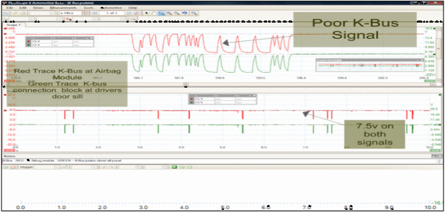
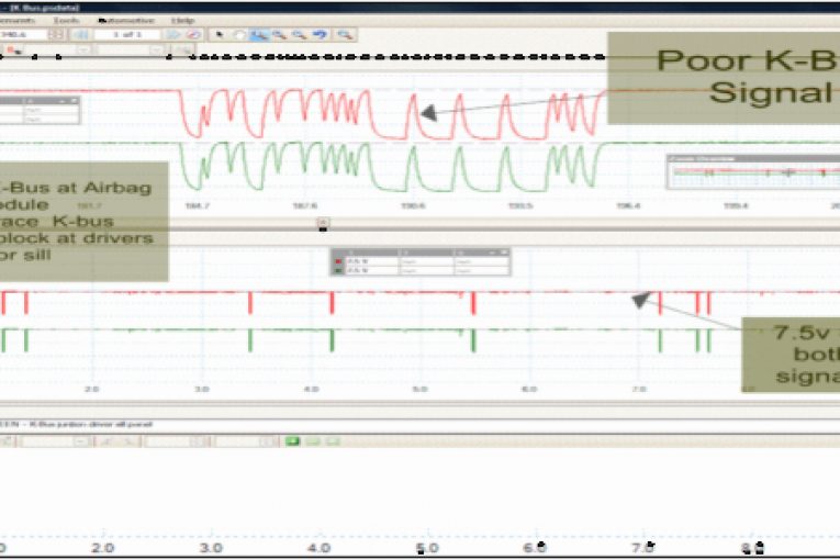
This capture is one single wire with the red trace showing K-Bus at the MRS module cavity 51 (airbag module) and the green trace showing K-Bus at the driver’s door sill. The top and bottom captures are the same. The top trace is a ‘zoomed’ version of the lower trace.
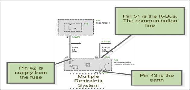
I first decided to check the 5A fuse (F18 for the MRS). It had a Nominal Battery Voltage (NBV) and was in good order, so the next stage was to get access to the MRS module. The module is located beneath the handbrake lever under the carpet and wasn’t easily accessible, so the front seats were removed and the carpet lifted from the rear seats to the front of the vehicle – this was just enough to access the module. With the diagram, I was able to check the cavities shown. The supply and earth was in good order.
I wanted to then check the communication line as we obviously had other modules that were not communicating. By attaching the PicoScope to cavity 51 of the MRS module I was able to see the K-Bus signal; I also located the K-Bus at the O/S/F door sill. By capturing the K-Bus we could see what was going on and something certainly was not right (see top capture of the three, pictured right). On this variant the K-Bus wire is white and red with a yellow band (WS/RT/GE).
After zooming in I could see that the data being sent was not correct and the input voltage of 7.5V was also incorrect. I was now getting somewhere, so having found our problem I just needed to locate the cause…
The cause becomes clear
Studying the wiring diagram led me to the BCM, which on this variant is located in the driver’s side foot-well. Upon removing the module I found water ingress and the wiring harness was soaked. After unplugging the harness the cause was very clear – the corrosion to the terminals at the BCM was so bad that when I unplugged it the pin had broken off.
In the real world this needed a new BCM and a wiring harness, but this is a sales car and car salesmen rarely want to spend money… so I came up with a plan!I opened the BCM and followed the pin back before soldering a wire to the good part inside the BCM and attaching the wire to the other side of the multi-plug.
After refitting the BCM I carried out a global scan which gave me full communication to all modules, the TPMS reset and all was looking good. I then attached the scope to the K-Bus again for good measure and the repair was confirmed a success.
Understanding the system
The main conclusion that I could draw from this job was that perhaps the mobile company who looked at this first are more in the market for quick repairs or did not have the confidence to take on the repair. My answer to this is that once the system is understood, the process then becomes much easier. It just goes to show that one device is often not enough…
K-BUS explained…
K-Bus consists of a single copper wire, data transfer is approx 9.6Kps (Bits Per Second) and is always active when terminal R is switched on. If the bus line is quiet for more than 60 seconds all the control modules that are connected will go into ‘sleep’ mode. The wire colour is uniform throughout the vehicle, WS/R T/GE (White/Red/Yellow).
Due to the linear structure of the network, K-Bus is available for other modules in the event of a disconnection or failed control unit. Just like the CAN Bus, this is referred to as a ‘tree structure’ with each control unit occupying a branch. The K-Bus provides a diagnostic connection to the control unit connected on those busses and uses only a determined controller to supply B+ for communication. The voltage level must be above 7V while the nominal voltage should be close to NBV. In my experience a good working K-Bus is around 13V.


