
Although an ordinary multimeter is often enough to diagnose voltages and currents flowing through a vehicle’s electrical wiring, there are some situations where an advanced multi-channel oscilloscope is necessary to conduct measurements. This is particularly relevant for quick change signals from Hall or magnetic-inductive sensors and control signals for actuators, such as injectors, valves, fans or data transmission.

Testing an ignition coil
The only reasonable method of achieving this is to check the coil’s behaviour with an oscilloscope. In the following examples the coil is connected to the oscilloscope of the CDIF/3 Expert diagnostic program from AXES System. In the CDIF/3, each of the controller and generator outputs has its own dedicated oscilloscope channel.
TEST SCENARIO 1
Problem with tester communication when the engine is ON. The tester works properly with the ignition switched ON.
1. Connect the ignition coil to the appropriate outputs of the controller – power supply to output A, ground to output B and control to output D.
2. In the software activate the individual channels using the Controller tool. Set the coil dwell time in channel D to 2ms.

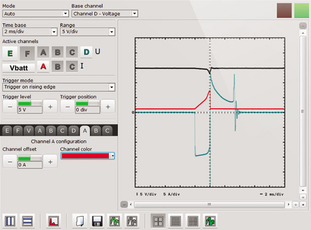
3. In the oscilloscope set the time base to 2ms and the measuring range to 5V/div. Active channels can be seen below, and here you can activate the individual channels. Two large buttons – E and F – are used to start measurements via the BNC connectors located in the CDIF’s housing. Channels A, B, C and D marked with the letter U are used to measure changes in voltage vs. time, whereas the channels A, B and C marked with the letter I are used to measure changes in current vs. time. The only remaining channel – Vbatt – shows the battery voltage level.
4. For the purposes of this example three channels have been activated respectively: Channel D (U) to observe the ignition coil control with ground signal pulses (pulse width: 2 ms); channel A (I) showing the current consumption (approx. 6A) during the coil dwell time; and the Vbatt channel shows the effect of the voltage pulsation in the power supply system during the coil dwell time.
The resultant effect often leads to the termination of communication with an on-board control unit during engine operation. The communication problem, however, did not occur with the ignition ON.
TEST SCENARIO 2
Irregular engine running and ‘misfiring’ – usually caused by an improper fuel mixture combustion or afterburning of fuel in the exhaust pipe and the catalytic converter.
1. Similar to the first example, connect the coil to the appropriate outputs of the controller.
2. In the Controlller tab, the coil dwell time is changed to 4ms.
3. Try to observe the oscilloscope capture of the overloaded ignition coil (below). The registered image shows a sloping chart in the Channel D (U) used for the coil dwell observation. A voltage surge to the power supply level can be noticed in the second milisecond (the ground is connected all the time).
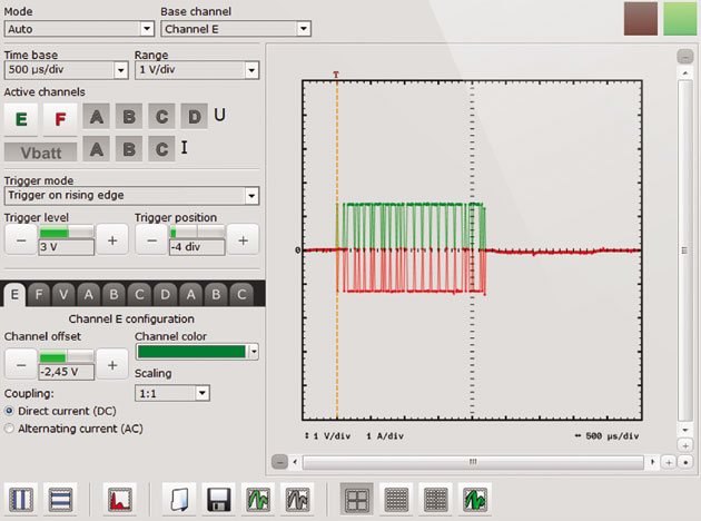
4. At the same time the dwell current drops to approx. 3/4 of its maximum value since the coil is already dwelled up. Further voltage drop continues in the Vbatt channel to reach a dangerous level of approx. 8V.
This effect may lead to defects in the engine control module (ignition coil control power output).


