
Laser Tools provides us with a step-by-step guide to installing its engine and gearbox support tool, which will allow easier access for technicians when vehicles are mounted.
On transverse engine vehicles, when carrying out repair operations such as clutch or gearbox removal, a common method for supporting the engine is a transmission jack. This method has one big disadvantage however; once the jack is in place the hoist cannot be lowered or raised. Laser Tools has developed an engine and gearbox support tool that is designed to alleviate this problem (part number 5750).
As well as being a terrific time saver, the support beam makes things accessible, and difficult jobs become easy. This is obviously a great advantage when removing engine mounts to gain access during a cam belt change, for example.
Installation
■ Set initial adjustment with the support frame on the floor under the vehicle before lifting into position. Initially set the engine/transmission support pad low to assist fitting.
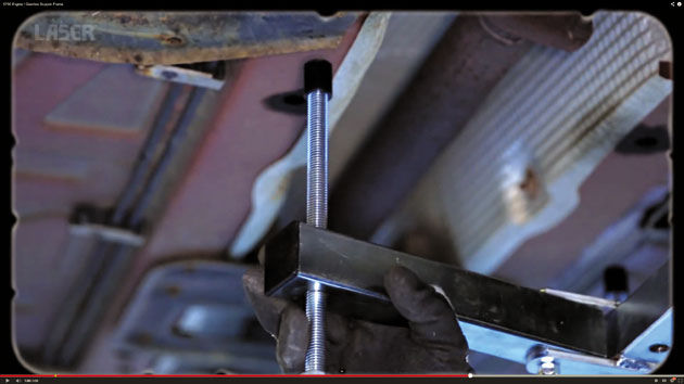
■ To enable the frame length to be extended, first release the spring loaded safety lock, then when correct length is reached, lock frame with the sliding frame locking screw.
■ The mounting support hooks are hooked over the main engine/transmission support cross-member, either over the edge of the cross-member or through convenient access holes.
Slide the hooks along the frame to the desired position then secure by tightening the locking screws. Hooks can then be adjusted up or down to attach to the cross-member, then secured when in the correct position.
■ Thrust pins can be mounted in two positions in the adjustable arms, offering maximum flexibility in choice of location. The weight of the engine or transmission being supported is transferred across the frame to the thrust pins. Position the thrust pins by choosing strong, supported areas of the floorpan, bulkhead or transmission tunnel, to bear this weight.
■ Then adjust the engine/transmission support pad up onto a suitable area on the engine or transmission being supported. The pad is easily adjusted once work is underway, for example when replacing an engine mounting.
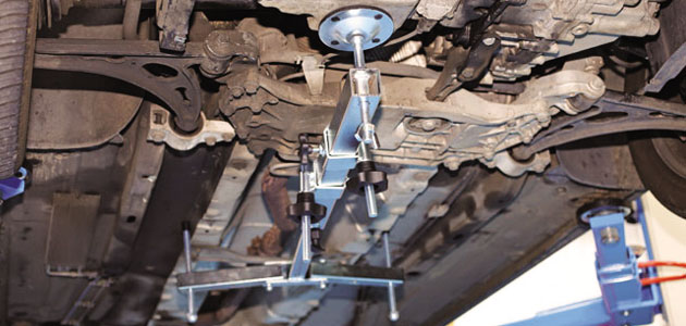
Step 1 – The support frame is quickly and easily fitted,
and the engine or gearbox height can be adjusted from underneath.
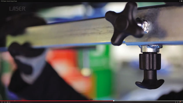
Step 2 – It features a safety locking mechanism that ensures it does not come apart while fitting.
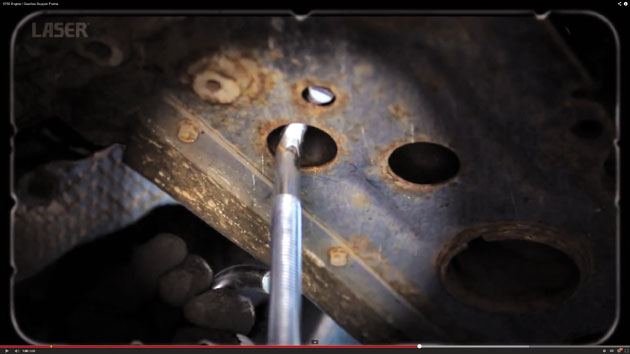
Step 3 – The frame hooks under and pivots on the main cross-member.
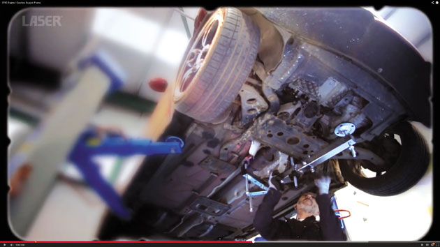
Step 4 – Then the weight of the engine is transferred to the support legs.
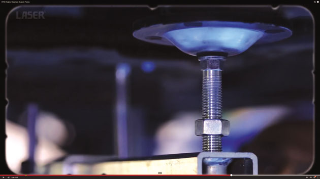
Step 5 – This lets the engine or gearbox height be easily adjusted from underneath.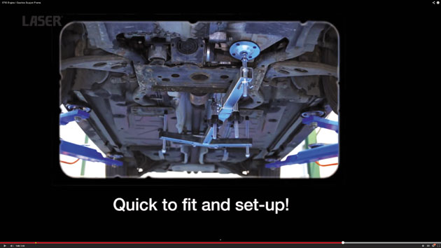
Step 6 – Once locked into position, the engine or gearbox is
safely supported and the vehicle hoist can be lowered or raised.


